Overview of the Working Principle of Finned Tube Heat Exchanger
I. Finned Tube Heat Exchanger Overview
Our company produces various specifications of finned tube heat exchangers, including various standard and non-standard models. The main models of finned tube heat exchangers include SRZ, SRL, GLII, FUL, KL, and many others. We offer options for users to design and process non-standard models such as floating head heat exchangers, stainless steel heat exchangers, steam heat exchangers, steel-aluminum composite heat exchangers, etc.
II. Working Principle of Finned Tube Heat Exchanger
The finned tube heat exchanger belongs to a type of enhanced heat transfer exchanger, relying on external fins to enhance heat transfer on the air side. It is a cost-effective choice for situations where air is heated by steam or thermal oil. Depending on process conditions, various types of finned tube heat exchangers can be used, such as steel tubes wound with steel fins, steel tubes wound with aluminum fins, copper tubes with aluminum fins, and bimetallic fins of steel-aluminum composites.
III. Characteristics of Steel-Aluminum Composite Fins Tube
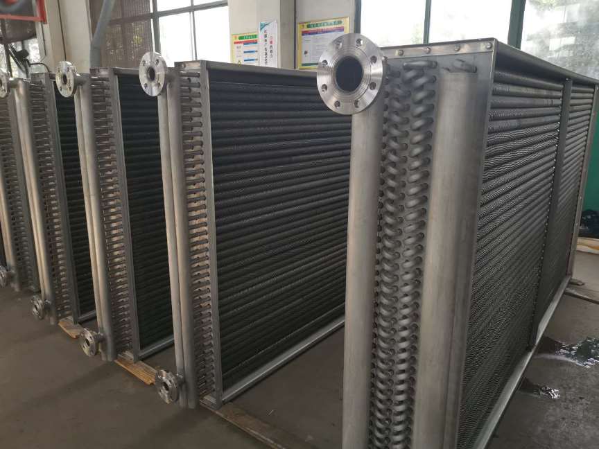
The heat exchanger utilizes steel-aluminum composite fins as the main heat exchange elements. Due to the advanced composite process, there is minimal thermal resistance below 210 degrees Celsius inside the tube. The radiator combines the pressure resistance of steel tubes with the high thermal conductivity of aluminum, resulting in excellent heat transfer performance. It avoids direct contact between steel tubes and air, improving corrosion resistance. The fin design minimizes air resistance, and the structure is easy to clean, compact, with a large unit heat transfer area.
External parameters include tube diameter, fin pitch, row pitch, spacing, aluminum fin thickness, air volume, wind speed, etc.
IV. Heat Transfer Capacity of Finned Tube Heat Exchanger
Lets discuss the impact of changes in external parameters on the performance of finned tube heat exchangers. The following conclusions, obtained through software simulation analysis from relevant literature, compare heat transfer effects under different conditions:
1. Under the same finned tube heat exchanger structure, higher face wind speed leads to better heat transfer, but it also increases air resistance and fan power. This applies to evaporators, condensers, and coolers.
2. At the same face wind speed, increasing fin spacing reduces heat transfer area and heat transfer capacity. However, the reduction in air resistance due to increased fin spacing decreases fan power. In some cases, the overall heat transfer capacity increases, reaching a maximum value between 1.8-2.0mm for condensers and 1.9mm-2.1mm for evaporators.
3. Increasing fin width, under the same conditions of fin spacing and face wind speed, slightly increases heat transfer capacity due to the larger radiating area. However, the average heat transfer coefficient on the fin surface decreases, leading to a slight decrease in heat transfer per unit area. Still, the overall heat transfer capacity increases due to the larger heat transfer area.
V. Advantages of Finned Tube Heat Exchanger
1. Uses phase change of the working medium for heat transfer, greatly increasing the heat exchange surface with fins on the outside. This design is very economical for recovering low-grade thermal energy. Additionally, the finned tube heat exchanger easily achieves vertical or inclined flow on the tube exterior and pure counterflow of hot and cold fluids, enhancing the average temperature and pressure of heat transfer without changing the inlet temperature of hot and cold fluids.
2. The heat exchange surfaces on both sides can be freely arranged. The finned tube heat exchangers heat exchange element is the finned tube, and the lengths of the evaporation and condensation sections are independently determined based on given heat transfer, fluid temperatures, flow rates, and the properties and cleanliness of each fluid on both sides. The two sides are not interlinked structurally, ensuring the finned tube heat exchanger is suitable for heat transfer between two fluids with disparate temperatures, flow rates, and cleanliness.
3. Ensures no mixing of two fluids when local heat transfer surface damage occurs. During operation, the two media are completely separated, and if a single finned tube fails due to wear, corrosion, or overheating, only that heat pipe is affected without mixing of hot and cold fluids. This design ensures high reliability, especially for flammable, explosive, or corrosive fluid heat exchange applications.
4. Has a high ability to resist ash accumulation. The flow of flue gas over the tube exterior enhances gas disturbance, and since the tube wall temperature is high, the tube remains dry. This prevents coking and ash adhesion, effectively preventing blockages.
5. Exhibits efficient resistance to low-temperature corrosion. When used for recovering the waste heat of corrosive flue gas, adjusting the heat transfer area can regulate the tube wall temperature to avoid the most corrosive areas.
Fin Tube Heat Exchanger |