T-finned tube not only low fin tube
T-finned tubes definition
A T-finned tube is a heat transfer component formed by rolling a base tube to create integral fins that project radially outward in a "T" profile. The fin geometry increases the effective heat exchange surface while preserving a compact envelope. This configuration is especially valued in applications where space is constrained but thermal performance cannot be compromised.
The T-shaped fin contour offers a balance between extended surface area and mechanical robustness. Unlike plain tubes, the fins act as heat-dissipating extensions that improve the thermal coupling between the tube wall and the surrounding fluid or air. The rolling process used to manufacture these tubes produces a continuous spiral fin structure, which ensures uniform heat transfer along the tube length.
T type finned tube structure
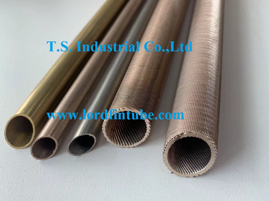
Which structural elements define a T type finned tube? The most distinctive feature is the fin cross-section, which resembles the letter "T". The top flange of the fin is wider than the stem, creating a mushroom-like profile. This shape provides enhanced stiffness compared to rectangular or L-shaped fins, allowing the tube to withstand higher external pressures and reducing the risk of fin deformation under thermal cycling or mechanical vibration.
The fins are formed from the same material as the base tube through a cold-rolling process. This method produces a metallurgical bond between the fin and the tube wall, eliminating the need for brazing or welding. The resulting structure has no contact resistance at the fin–tube interface, which is a critical advantage for heat conduction. Typical materials include copper, copper alloys, carbon steel, and stainless steel, with selection based on the operating environment and fluid compatibility.
T-finned tubes working mechanism
How does a T-finned tube achieve its thermal performance? The underlying principle is straightforward: the fins multiply the external surface area available for heat exchange. When a hot fluid flows through the tube, heat conducts radially through the tube wall and then along the fins, where it is transferred to the ambient medium—whether air, water, or a process fluid.
For boiling applications, the T-shaped fin geometry creates a series of spiral tunnels on the outer surface. These tunnels act as nucleation sites for vapor bubbles. When the heat medium outside the tube heats the surface, bubble nuclei form within the T-shaped cavities. Because the cavities are surrounded by heated walls, the bubbles expand rapidly, filling the tunnel volume. As the bubbles grow, internal pressure rises, and they are expelled forcefully through the narrow slit openings between adjacent fins. This ejection creates localized turbulence and partial vacuum, drawing cooler liquid into the tunnels and sustaining a continuous boiling cycle. In this manner, the T-finned tube removes substantially more heat per unit surface area per unit time than a bare tube of equivalent diameter.
This boiling enhancement is particularly effective when the shell-side medium is relatively clean—free from solids, scale-forming compounds, and sticky gums. Under such conditions, the T-finned tube can operate as a high-efficiency boiling heat exchanger component, significantly improving the shell-side heat transfer coefficient.
T-finned tubes technical specifications
Below are typical design parameters for T-finned tubes. Actual values depend on the tube diameter, material, and intended service conditions.
Fin height1.0 – 2.5 mm
Fin thickness (tip)0.3 – 0.8 mm
Fin pitch (spacing)0.8 – 2.0 mm
Base tube O.D.12.7 – 50.8 mm
Wall thickness (base)0.8 – 3.0 mm
Fin surface area ratio2.5 – 4.0 × bare tube
MaterialsCopper, brass, carbon steel, SS304/316
Max. operating temp.up to 400 °C (depending on material)
| Parameter |
Value range |
Remarks |
| Tube O.D. (base) |
12.7 – 50.8 mm |
Custom sizes available |
| Fin O.D. |
14.7 – 55.8 mm |
Depends on fin height |
| Fin density |
500 – 1200 fins per meter |
Based on pitch |
| Wall thickness |
0.8 – 3.0 mm |
Pressure-rated designs |
| Max. pressure |
up to 10 MPa |
Material dependent |
T-finned tubes applications
Where are T-finned tubes most commonly deployed? Their ability to combine high surface area with mechanical strength makes them suitable for a wide range of industrial and commercial systems.
- Heat exchangers – used in air-conditioning, refrigeration, and industrial process cooling, where the fins improve the thermal link between the tube-side fluid and the external air or water stream.
- Boilers – installed in fire-tube and water-tube boilers to maximize heat recovery from combustion gases, increasing overall thermal efficiency.
- Air coolers – employed in power plants, refineries, and petrochemical facilities to cool process fluids or gases using ambient air as the cooling medium.
- Radiators – found in automotive and stationary engine cooling systems, where the fins dissipate heat from the coolant to the surrounding air.
- Heat recovery systems – integrated into waste-heat recovery units to capture thermal energy from exhaust streams and repurpose it for preheating or other process needs.
- Evaporators and condensers – utilized in refrigeration cycles and HVAC systems, where the enhanced surface area facilitates efficient phase-change heat transfer during evaporation and condensation.
In each of these applications, the T-finned tube delivers measurable improvements in heat transfer performance, which can translate into smaller equipment footprints, lower energy consumption, and reduced operating costs.
T-finned tubes versus plain tubes
How does a T-finned tube compare with a plain tube of the same diameter and wall thickness? The table below highlights the key differences in thermal and mechanical performance.
| Aspect |
T-finned tube |
Plain tube |
| External surface area |
2.5 – 4.0 × higher |
Base reference |
| Overall heat transfer coefficient (air side) |
40 – 80 % higher |
Baseline |
| Boiling heat flux (shell side) |
3 – 5 × higher |
Baseline |
| Mechanical strength (fin rigidity) |
High (T-profile) |
N/A |
| Pressure drop (shell side) |
Moderately higher |
Lower |
| Fouling tendency |
Moderate (clean fluids preferred) |
Low |
| Cost |
Higher (rolling process) |
Lower |
While the initial cost of a T-finned tube is greater than that of a plain tube, the performance gains often justify the investment in applications where thermal efficiency, space constraints, or energy savings are critical.
Practical note: For optimal performance, T-finned tubes should be specified for shell-side media that are relatively clean—free from suspended solids, sticky residues, and high-fouling compounds. When these conditions are met, the enhanced boiling and convective heat transfer characteristics of the T-fin design deliver substantial efficiency gains. Engineers are advised to evaluate the fluid properties and operating parameters carefully to select the appropriate fin density, height, and material.
T-finned tube heat exchanger components — for additional product details and technical support, please consult the manufacturers documentation.