ASTM B395 Standard Specification for U-Bend Seamless Copper and Copper Alloy Heat Exchanger and Condenser Tubes
1. ASTM B395 Scope
1.1 This specification2 covers U-bend seamless condenser, evaporator, and heat exchanger tubes of copper and copper alloys up to 2 in., inclusive, in diameter. Tubes for this application are normally made from the following copper or copper alloys:
Copper or Copper Alloy Previously Used
UNS No.3 Designation Type of Metal
C10200 OFA oxygen-free without residual deoxidants
C10300 oxygen-free, extra low phosphorus
C10800 oxygen-free, low phosphorus
C12000 DLPA phosphorized, low residual phosphorus
C12200 DHPA phosphorized, high residual phosphorus
C14200 DPAA phosphorized, arsenical
C19200 ... phosphorized, 1 % iron
C23000 ... red brass
C44300 Types B, admiralty metals
C44400 C,
C44500 D
C60800 ... aluminum bronze
C68700 Type B aluminum brass
C70400 ... 95-5 copper-nickel
C70600 ... 90-10 copper-nickel
C71000 ... 80-20 copper-nickel
C71500 ... 70-30 copper-nickel
C72200 ... copper-nickel
2. ASTM B395 Referenced Documents
2.1 The following documents of the issue in effect on date of material purchase form a part of this specification to the extent referenced herein:
2.2 ASTM Standards:
B 153 Test Method for Expansion (Pin Test) of Copper and Copper-Alloy Pipe and Tubing4
B 154 Test Method for Mercurous Nitrate Test for Copper and Copper Alloys4
B 170 Specification for Oxygen-Free Electrolytic Copper Refinery Shapes4
B 224 Classification of Coppers4
B 601 Practice for Temper Designations for Copper and Copper Alloys—Wrought and Cast4
E 8 Test Methods for Tension Testing of Metallic Materials5
E 29 Practice for Using Significant Digits in Test Data to Determine Conformance with Specifications6
E 53 Test Methods for Chemical Analysis of Copper7
E 54 Test Methods for Chemical Analysis of Special Brasses and Bronzes7
E 55 Practice for Sampling Wrought Nonferrous Metals and Alloys for Determination of Chemical Composition7
E 62 Test Methods for Chemical Analysis of Copper and Copper Alloys (Photometric Methods)
E 75 Test Methods for Chemical Analysis of Copper-Nickel and Copper-Nickel-Zinc Alloys7
E 112 Test Methods for Determining Average Grain Size5
E 243 Practice for Electromagnetic (Eddy-Current) Examination of Copper and Copper-Alloy Tubes8
E 478 Test Methods for Chemical Analysis of Copper Alloys9
E 527 Practice for Numbering Metals and Alloys (UNS)10
3. ASTM B395 Terminology
3.1 Definitions of Terms Specific to This Standard:
3.1.1 Capable of—as used in this specification, the test need not be performed by the producer of the material. However, should subsequent testing by the purchaser establish that the material does not meet these requirements, the material shall be subject to rejection.
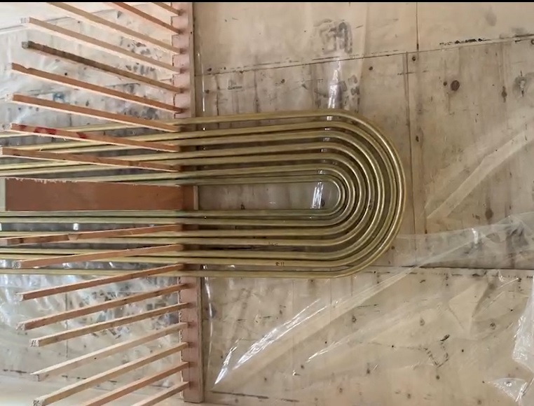
3.1.2 U-Bend Tube—a tube bent 180° in a single plane into a U-shape.
4. ASTM B395 Ordering Information
4.1 Orders for U-bend tubes under this specification shall include the following information:
4.1.1 Material (Sections 5 and 6),
4.1.2 Temper (Section 7),
4.1.3 Whether tension test is required (Section 8),
4.1.4 Whether the U-bent portion of copper-nickel U-bend tubes is to be relief annealed (see 7.4),
4.1.5 Dimensions: diameter and wall thickness of tube (see 14.1 and 14.2),
4.1.6 Schedule of tubes required in dual gage and length of heavy gage section (see 5.2 and 14.3),
4.1.7 Schedule of bending radii (see 14.5),
4.1.8 Length of U-bend tube legs (see 14.8),
4.1.9 Certification, if required (see 22.1), and
4.1.10 Mill Test Report, if required (see 23.1).
4.1.11 If the product is to be subsequently welded (see Table
2, Footnote C).
4.2 In addition, when material is purchased for agencies of the U.S. Government, it shall conform to the Supplementary Requirements as defined herein when specified in the contract or purchase order.
5. ASTM B395 Materials and Manufacture
5.1 The material shall be of such quality and purity that the finished product shall have the properties and characteristics prescribed in this specification.
5.2 Tubes required to be U-bent to a small radius shall, if specified, be furnished as dual gage tubes. These tubes shall be made prior to U-bending with the wall thickness of the central section of the tube length, thickened to the equivalent of one Stubs’ or Birmingham Wire (Bwg) gage heavier than the wall thickness specified for the straight leg portion of the U-bend tube. Unless otherwise specified, dual gage tubes shall be made to constant inside diameter; that is, the increased wall thickness shall be obtained by increasing the outside diameter of the finished tube in the central heavy gage section.
5.3 The bent portion of the U-bend tube shall be substantially uniform in curvature.
6. ASTM B395 Chemical Composition
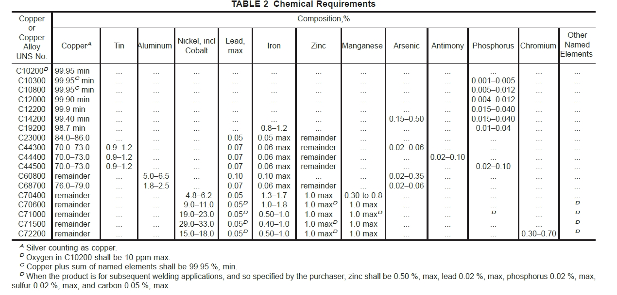
6.1 The material shall conform to the chemical requirements specified in Table 2.
6.2 These specification limits do not preclude the presence of other elements. Limits for unnamed elements may be established by agreement between manufacturer or supplier and purchaser.
6.2.1 Copper Alloy UNS No. C19200—Copper may be taken as the difference between the sum of all the elements analyzed and 100 %. When all the elements in Table 2 are analyzed, their sum shall be 99.8 % minimum.
6.2.2 For copper alloys in which copper is specified as the remainder, copper may be taken as the difference between the sum of all the elements analyzed and 100 %.
6.2.2.1 When all the elements in Table 2 are analyzed, their sum shall be as shown in the following table.
Copper Alloy UNS No. Copper Plus Named Elements, % min
C60800 99.5
C70400 99.5
C70600 99.5
C71000 99.5
C71500 99.5
C72200 99.8
6.2.3 For copper alloys in which zinc is specified as the remainder, either copper or zinc may be taken as the difference between the sum of all the elements analyzed and 100 %.
6.2.3.1 When all the elements in Table 2 are analyzed, their sum shall be as shown in the following table.
Copper Alloy UNS No. Copper Plus Named Elements, % min
C23000 99.8
C44300 99.6
C44400 99.6
C44500 99.6
C68700 99.5
7. ASTM B395 Temper (see Practice B 601)
7.1 Prior to U-bending, tubes of Copper Alloy UNS Nos.
C23000, C44300, C44400, C44500, C60800, C68700, C70400, C70600, C71000, C71500, and C72200 shall be in the annealed temper (O61), unless otherwise specified in the purchase order.
7.2 Prior to bending, U-bend tubes of Copper Alloy UNS Nos. C10200, C10300, C10800, C12000, C12200, and C14200 shall normally be in light drawn temper (H55). Tubes of Copper Alloy UNS Nos. C70400, C70600, and C72200 shall, if specified, be made in the light-drawn temper (H55).
7.3 Prior to bending, U-bend tubes of Copper Alloy UNS No. C19200 shall normally be in the annealed (O61) or light drawn temper (H55) as specified.
7.4 Prior to bending, U-bend tubes of Copper Alloy UNS No. C71500 shall, if specified, be made in the drawn, stress relieved temper (HR58).
7.5 The U-bend portion of tubes furnished in Copper Alloy UNS Nos. C23000, C44300, C44400, C44500, C60800, and C68700 shall be relief annealed (HR) after bending. If specified, the U-bend portion of tubes furnished in Copper Alloy UNS Nos. C70400, C70600, C71000, C71500, and C72200 shall be relief annealed (HR) after bending.
8. Tensile Properties
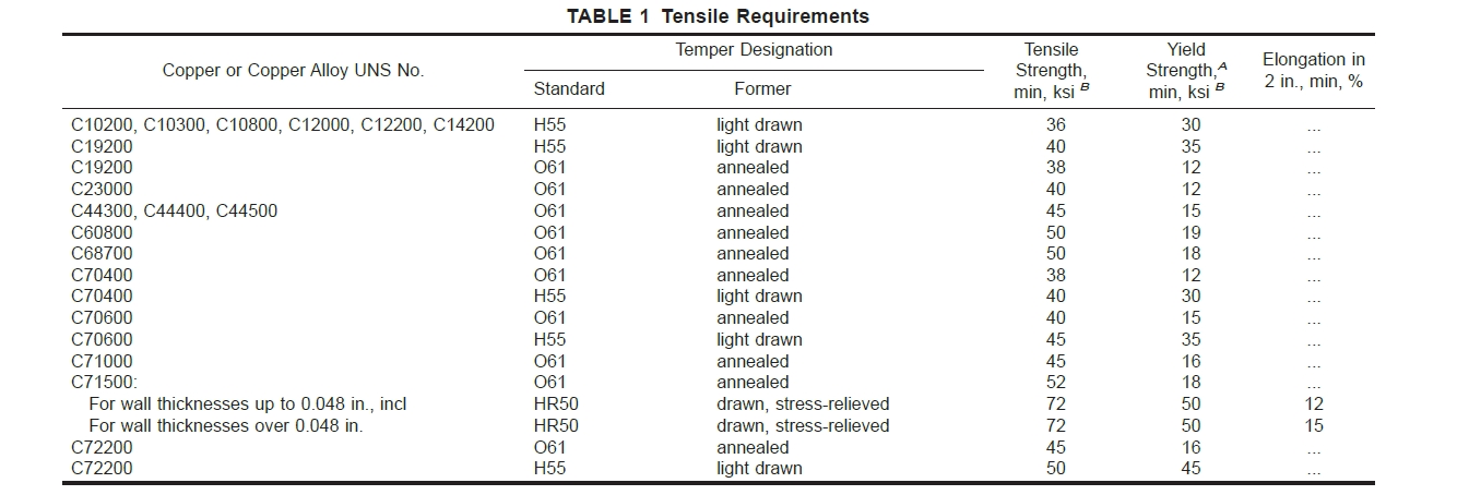
8.1 Material specified to meet the requirements of the ASME Boiler and Pressure Vessel Code shall have tensile properties as prescribed in Table 1.
9. ASTM B395 Microscopical Examination
9.1 Samples of annealed-temper (O61) tubes selected for test shall be subjected to microscopical examination at a magnification of 75 diameters and shall show uniform and complete recrystallization. Materials other than Copper Alloy UNS No. C19200 shall have an average grain size within the limits of 0.010 to 0.045 mm. The requirements of Section 9 do not apply to tubes of light-drawn (H55), drawn, stress-relieved (HR58) or to the U-bent portion.
10. ASTM B395 Expansion Test
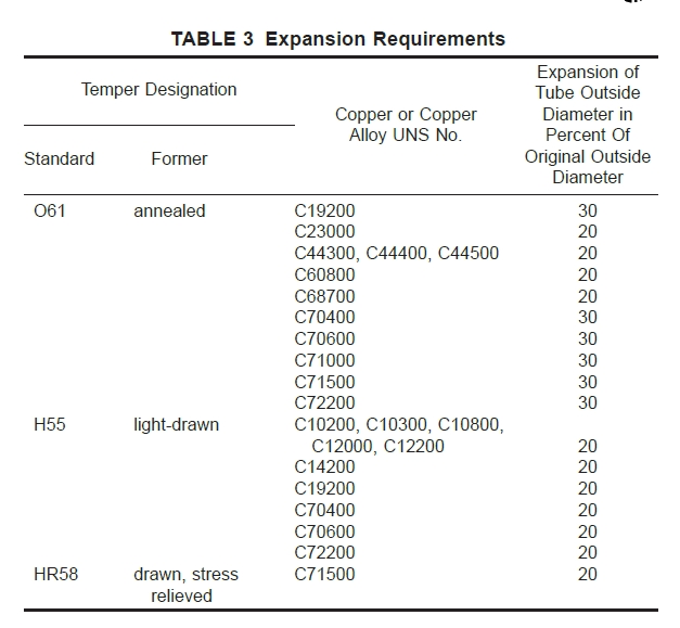
10.1 Tube specimens selected for test shall withstand the expansion shown in Table 3 when expanded in accordance with Test Method B 153. The expanded tube shall show no cracking or rupture visible to the unaided eye.
NOTE 4—The term “unaided eye” as used herein permits the use of corrective spectacles necessary to obtain normal vision.
11. ASTM B395 Flattening Test
11.1 Test specimens shall be flattened on at least three different elements throughout the lengths remaining after the specimens for the expanding and metallographic tests have been taken. For tube in the light-drawn (H55) and drawn, stress-relieved (HR58) tempers the specimens shall be annealed prior to flattening. Each element shall be slowly flattened by one stroke of a press. The length of each flattened element shall be at least 2 in. The term flattened shall be interpreted as follows: A micrometer caliper set at three times the wall thickness shall pass over the tube freely throughout the flattened part except at the points where the change in element of flattening takes place. The flattened elements shall not show cracking or rupture clearly visible to the unaided eye (Note 3).
12. ASTM B395 Mercurous Nitrate Test
12.1 Warning—Mercury is a definite health hazard and therefore equipment for the detection and removal of mercury vapor produced in volatilization is recommended. The use of rubber gloves in testing is advisable.
12.2 A sufficient length of tube taken from each of the two sample lengths selected for test specimens shall be U-bent to the smallest radius in the order and shall be subjected to the same relief anneal (HR) treatment to be used for this size in producing the order. The test specimens, cut 6 in. in length from both the U-bend and straight leg length, shall stand without cracking, an immersion in the standard mercurous nitrate solution in Test Method B 154; the straight leg specimens shall include the finished tube ends. The mercurous nitrate test is required only for Copper Alloy UNS Nos. C23000, C44300, C44400, C44500, C60800, and C68700.
NOTE 5—There is no standard test method to evaluate the effectiveness of a relief anneal (HR) of the U-bent section of copper-nickel or copper-nickel-iron tubes with respect to stress-corrosion cracking susceptibility.
13. ASTM B395 Nondestructive Testing
13.1 Eddy-Current Test:
13.1.1 Each tube, prior to bending, shall be subjected to the eddy-current test. Tubes may be tested in the final drawn, annealed, or heat-treated temper or in the drawn temper prior to the final anneal or heat treatment unless otherwise agreed upon by the supplier and the purchaser.
13.1.2 Each tube shall be passed through an eddy-current testing unit adjusted to provide information on the suitability of the tube for the intended application. Testing shall follow the procedures of Practice E 243.
13.1.3 The depth of the round-bottom transverse notches and the diameters of the drilled holes in the calibrating tube used to adjust the sensitivity of the test unit are shown in Table 4 and Table 5, respectively.
13.1.4 Tubes that do not actuate the signaling device of the eddy-current tester shall be considered as conforming to the requirements of this test. Tubes causing irrelevant signals because of moisture, soil, and like effects may be reconditioned and retested. Such tubes, when retested to the original test parameters, shall be considered to conform if they do not cause output signals beyond the acceptable limits. Tubes causing irrelevant signals because of visible and identifiable handling marks shall be considered to conform if the tube dimensions are within the prescribed limits and if the tubes conform to the leak test requirements of 13.2.1.1 or 13.2.1.2, unless otherwise agreed to by the manufacturer and purchaser.
13.2 Other Tests:
13.2.1 Each U-Bend tube shall be tested to the requirements of 13.2.1.1 or 13.2.1.2. Unless otherwise specified, the manufacturer shall have the option of the leak test to be used.
13.2.1.1 Hydrostatic Test—Each tube shall stand, without showing evidence of leakage, an internal hydrostatic pressure sufficient to subject the material to a fiber stress of 7000 psi, determined by the following equation for thin hollow cylinders under tension. The tube need not be tested at a hydrostatic pressure of over a gage pressure of 1000 psi unless so specified.
P 5 2St/~D 2 0.8t! (1)
where:
P 5 hydrostatic pressure, psi,
t 5 thickness of tube wall, in.,
D 5 outside diameter of the tube, in., and
S 5 allowable stress of the material, psi.
13.2.1.2 Pneumatic Test—Each tube shall be subjected to an internal air gage pressure of 60 psi, minimum, for 5 s without showing evidence of leakage. The test method used shall permit easy visual detection of any leakage, such as by having the tube under water or by the pressure differential method. Any evidence of leakage shall be cause for rejection.
14. ASTM B395 Dimensions, Weights, and Permissible Variations
14.1 Tube Diameter—The outside diameter of the straight leg portion of the tube, exclusive of the central heavy gage
Standard ASTM B395 download Links
ASTM B395 Condenser Tubes