










What Are Hot Dipped Galvanized Elliptical Fin Tubes?
Hot dipped galvanized elliptical fin tubes are heat-transfer elements built from an oval (flattened) carbon steel base tube with rectangular steel fins fitted along its length, then immersed as a complete assembly in molten zinc. The zinc bath coats the tube and every fin surface, including the fin-to-tube contact line, producing a continuous sacrificial layer that resists atmospheric and process-side corrosion.
The elliptical geometry is the reason engineers specify this component instead of a plain round fin tube. Flattening the tube reduces the frontal height of the bundle for the same flow area, which lowers air-side pressure drop and allows a more compact exchanger casing. In refinery air coolers, petrochemical convection sections, steel mill recuperators and gas preheaters, that combination of low pressure loss and galvanized corrosion protection is often the deciding factor.
This page describes the construction, verifiable parameters, manufacturing route, selection boundaries and inspection documentation for hot dipped galvanized elliptical fin tubes. The finished component is catalogued as an elliptical (oval) fin tube; related round and helical variants are listed under elliptical finned tube and elliptical finned tubes.
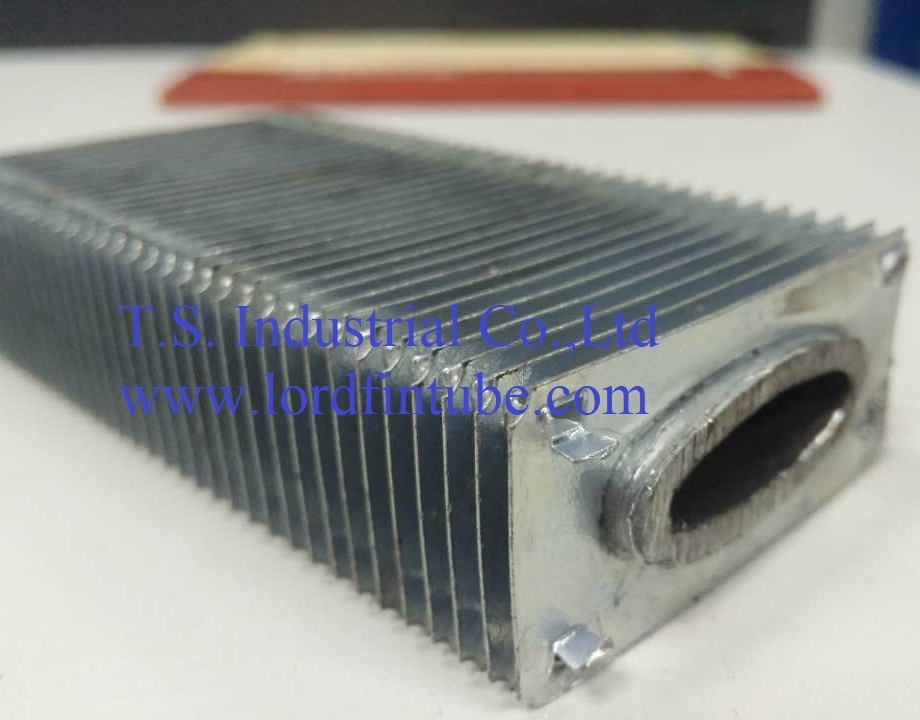
Product Identity: What the Finished Tube Actually Is
Buyers and search engines should be able to confirm the identity of this component from the text alone. A hot dipped galvanized elliptical fin tube consists of four verifiable elements:
- Base tube: carbon steel, seamless or welded, flattened to an oval section. Nominal axes are approximately 36 mm (long) and 14 mm (short), with tolerance agreed per project specification.
- Fins: rectangular SPCC cold-rolled steel strip, typically 55 × 26 × 0.25 mm, punched as individual platelets and positioned at a fixed pitch along the tube.
- Bond: fins are mechanically or manually inserted under pressure so the fin collar grips the oval tube wall.
- Coating: hot dip galvanizing applied after fin assembly, so zinc covers the fin faces, fin edges and the base tube surface between fins.
The order of operations matters. Galvanizing after finning is what distinguishes this product from a pre-galvanized tube that is finned afterwards, where cut edges and insertion scratches remain unprotected.
Key Parameters and Their Units
Fin pitch (mm)
Fin pitch is the centre-to-centre distance between adjacent fins, expressed in millimetres. It controls how much surface area is packed into each metre of tube and how easily the air-side channel fouls. Supplied pitches typically include 2.3, 2.5, 2.8 and 3.2 mm; final pitch is confirmed against the project specification and the manufacturers data sheet.
Fin density (pcs/m)
Fin density is the number of fins per metre of tube length and is the inverse of pitch, rounded to the nearest whole fin. Typical range: about 302–455 fins/m across the pitch values above. Fin density is the number an inspector can physically count, which makes it one of the most reliable shop-floor verification checks.
Heat transfer area per metre (m²/m)
This is the total wetted surface — fin faces plus exposed base tube — presented per metre of tube length. Typical range for this configuration: about 0.85–1.15 m²/m. The figure is only comparable between suppliers if both use the same accounting basis (see the formula section below).
Zinc coating thickness (mm or µm)
Coating thickness is quoted either in millimetres or micrometres; 1 µm = 0.001 mm. Typical range: 0.05–0.07 mm, equivalent to 50–70 µm. Coating mass (g/m²) is a different unit used by some galvanizing standards and should not be converted and mixed without stating the conversion basis.
Tube axes and flattening ratio
The long axis and short axis of the oval section, both in millimetres, define the flattening ratio (short axis ÷ long axis). A lower ratio gives a slimmer bundle profile and lower pressure drop, but reduces the internal flow area and raises the risk of excessive wall thinning at the bend of the oval.
Turbulator quantity (pcs)
Internal turbulators — commonly 4, 10 or 26 pieces per tube depending on length and duty — promote turbulence on the tube-side fluid. More inserts improve tube-side heat transfer but increase tube-side pressure drop and cleaning difficulty.
How Heat Transfer Area per Metre Is Calculated
The surface area of a finned tube is not a single universal number; it depends on how fin edges, fin collars and bare tube sections are counted. The general relationship is:
A_total = N × A_f + A_bare
Where:
- N = fin density, fins per metre (pcs/m)
- p = fin pitch (mm)
- A_f = exposed surface area of one fin (m²), normally counted on both faces
- A_bare = exposed base tube surface between fins (m²/m)
- A_total = total heat transfer area per metre of tube (m²/m)
Worked example of the density step: at p = 2.3 mm, N = 1000 / 2.3 ≈ 435 fins/m. At p = 3.2 mm, N = 1000 / 3.2 ≈ 313 fins/m. This is why published area figures fall as pitch increases.
Two suppliers can quote different A_total values for the same tube if one counts only the projected fin footprint and the other counts both fin faces plus the inter-fin tube surface. Always ask which basis is used before comparing. Where a duty requires a guaranteed area, the basis should be written into the purchase specification and confirmed by the manufacturers calculation sheet.
Elliptical vs. Round Finned Tube: Comparison
| Comparison dimension | Elliptical (oval) fin tube | Round fin tube | Practical effect |
|---|---|---|---|
| Bundle frontal height | Lower for the same flow area | Higher | Smaller casing, easier retrofit into existing ductwork |
| Air-side pressure drop | Generally lower, better wake recovery behind the oval | Higher | Lower fan power or higher allowable face velocity |
| Tube-side flow area | Reduced by flattening | Full circular bore | Higher tube-side velocity and pressure drop for the same mass flow |
| Fouling behaviour on the air side | Straighter channels, less debris bridging | More recirculation zones | Longer cleaning intervals in dusty service |
| Fin attachment | Individual rectangular platelets, punched and inserted | Often helical winding or embedded fin | Different bond quality risks; insertion pressure must be controlled |
| Corrosion protection | Hot dip galvanized after assembly | Depends on specification | Full coverage including fin edges and contact lines |
Design Trade-offs to Resolve Before Ordering
Four parameters interact, and improving one usually costs something elsewhere.
- Fin pitch versus fouling. Tight pitch (2.3 mm) maximises area but narrows the air channel; in dust-laden or soot-blown service a wider pitch of 2.8–3.2 mm is often the more durable choice.
- Flattening ratio versus tube-side pressure drop. A flatter oval improves the air-side profile but reduces internal bore, raising tube-side velocity and pressure loss. Where the tube-side fluid is viscous or flow-limited, the trade-off must be checked by calculation.
- Zinc thickness versus fin definition. A heavier zinc layer gives longer corrosion life but can bridge or blunt the fin edges, slightly reducing effective area and increasing weight. Typical range of 0.05–0.07 mm balances the two; confirm the target with the coating standard applicable to the project.
- Turbulator count versus cleanability. More inserts raise tube-side heat transfer but obstruct mechanical cleaning and add pressure drop.
- Fin insertion force versus fin integrity. Manual insertion is lower cost but applies limited pressure and can leave loose fins; mechanical insertion produces a firmer bond at the cost of noise, tooling wear and higher equipment investment.
Technical Parameter Table
| Parameter | Unit | Typical range | Verification note |
|---|---|---|---|
| Fin pitch | mm | 2.3 / 2.5 / 2.8 / 3.2 | Measured over 10 consecutive fins |
| Fin density | pcs/m | 302–455 | Count per metre |
| Heat transfer area | m²/m | 0.85–1.15 | Confirm accounting basis |
| Base tube material | — | Carbon steel, seamless or welded | MTC with heat number |
| Base tube long axis | mm | 36 nominal | Tolerance per project specification |
| Base tube short axis | mm | 14 nominal | Tolerance per project specification |
| Fin material | — | SPCC cold-rolled steel | MTC with heat number |
| Fin size (L × W × t) | mm | 55 × 26 × 0.25 | Sample measurement |
| Zinc coating thickness | mm (µm) | 0.05–0.07 (50–70) | Coating thickness gauge, multiple points |
| Turbulator quantity | pcs | 4 / 10 / 26 | Per drawing |
| Unit weight | kg/m | Approx. 2.0–3.3 | Depends on pitch and turbulator count |
| Maximum tube length | mm | Up to 15,000 | Confirm handling and shipping limits |
Materials and Standards
Material selection for this product is deliberately narrow, because the galvanizing step requires a steel chemistry and surface condition that accepts a uniform zinc layer.
- Base tube: carbon steel, seamless or welded. Chemistry should be suitable for hot dip galvanizing; silicon and phosphorus content influence coating appearance and thickness and should be agreed before rolling.
- Fin strip: SPCC cold-rolled carbon steel, thickness 0.25 mm in the standard configuration.
- Coating: zinc applied by full immersion after fin assembly.
- Standards: to be confirmed against the project specification or the applicable standard nominated in the purchase order. Lordfintube does not substitute one standards coating requirement for another; where the project does not name a standard, the reference is written as "according to project specification" and agreed in writing before production.
Production Process
- Base tube preparation. Carbon steel tube is inspected, cut to length and flattened to the specified oval section.
- Fin punching. SPCC strip is punched into individual rectangular fins with a formed collar matching the oval tube profile.
- Fin insertion. Fins are positioned at the specified pitch by manual or mechanical insertion. Mechanical insertion applies higher pressure and produces a firmer fin-to-tube bond; manual insertion is lower cost but applies limited pressure and carries a higher risk of loose fins.
- Assembly inspection. Pitch, fin squareness, fin count per metre and overall length are checked before galvanizing.
- Surface preparation. Degreasing and pickling remove oil, scale and oxide so the zinc can metallurgically bond to the steel.
- Hot dip galvanizing. The complete finned assembly is immersed in molten zinc, withdrawn and drained, forming a coating on the tube, fin faces and fin edges.
- Cooling and finishing. Coating thickness is measured, and any run-off or drip artefacts are assessed against the agreed acceptance criteria.
- Final inspection and packing. Dimensional check, documentation review and protection for transport.
Where These Tubes Fit — and Where They Do Not
Typical applications
- Refinery air coolers and convection sections
- Petrochemical process heaters and waste heat recovery
- Steel mill recuperators and related furnace equipment
- Natural gas preheaters and gas cooling trains
- Power plant air preheaters and auxiliary coolers
- Pulp and paper mill heat recovery
- Textile and drying plant heat exchangers
Selection boundaries
- High tube-side pressure duty: the flattened section reduces internal flow area and wall uniformity; a round tube is usually preferable where tube-side pressure is the governing design case.
- Severe tube-side fouling: oval bores are harder to clean mechanically than circular bores.
- High-temperature service where zinc is not acceptable: zinc has a limited service temperature window; where process conditions or product purity rule out zinc contamination, a different coating or bare alloy tube should be considered.
- Aggressive chemical environments: galvanizing is a sacrificial barrier, not a substitute for stainless or alloy selection in acidic or chloride-rich streams. Confirm suitability with the responsible engineer.
Selection Guide: What to Specify
- Duty and fluid data: tube-side and air-side flow rates, inlet and outlet temperatures, allowable pressure drop on both sides.
- Geometry: fin pitch, fin density, tube length, number of rows and tubes per row.
- Coating: target zinc thickness range and the acceptance method (thickness gauge points, coating mass or visual criteria).
- Tube-side enhancement: whether turbulators are required, and if so how many per tube.
- Documentation: MTC grade, heat number traceability, third-party inspection requirement.
- Interfaces: tube end preparation, header or tube sheet connection details, and any bend or weld requirements.
Where two of these conflict — for example high fin density against a dusty air stream — the specification should state which requirement takes priority. That single sentence prevents most rework disputes.
Quality and Inspection
| Inspection item | What is checked | Reference basis |
|---|---|---|
| Material verification | Base tube and fin strip chemistry against MTC | EN 10204 3.1 MTC, heat number traceability |
| PMI | Alloy identity of incoming tube, where specified | Project specification |
| Hardness | Base tube hardness, where required | Project specification |
| Dimensional check | Long/short axis, fin size, fin pitch, fin density, overall length | Approved drawing |
| Coating thickness | Zinc layer on tube and fins at defined points | Coating standard named in the order |
| Fin bond check | Visual and manual assessment for loose fins | Agreed acceptance criteria |
| Third-party inspection | Witnessed testing at the buyers nominated agency | Purchase order |
Inspection scope is agreed per order. Items listed above are the common set; not every project requires all of them, and the final list is confirmed in the purchase specification.
Packing and Shipping
Galvanized fin tubes are vulnerable in transit mainly at the fin edges and at the tube ends, so packing is designed around mechanical protection rather than weight alone.
- Bundles strapped with wooden or plastic separators so adjacent fin edges do not rub.
- Tube ends capped or plugged to protect the bore and end preparation.
- Bundles lifted by sling at marked points; no direct chain contact with the zinc surface.
- Weather protection for sea freight, with ventilation to avoid condensation inside the wrapping.
- Marking with heat number, bundle number and dimension data for site reconciliation.
- Lengths up to 15,000 mm require open-top or flat-rack arrangements; the shipping method should be agreed at order stage.
Specific packing, marking and shipping requirements follow the purchase order and the logistics plan agreed with the buyer. Typical range practices above are indicative only.
Supplier Verification Signals
For a component that is fully coated before delivery, paperwork is the buyers main window into what happened in the shop.
- Material certificates: EN 10204 3.1 mill test certificates for base tube and fin strip, with heat numbers that trace back to the actual heats used.
- Traceability: heat number marked on the bundle and carried through to the inspection record, so a delivered tube can be linked to its steel.
- Available inspection: PMI, hardness testing, dimensional measurement and third-party witnessed inspection on request.
- Certification held: ISO 9001:2015, valid until 21 August 2028.
- Welding and heat treatment records: where the tube ends are welded or the assembly receives any thermal treatment, PWHT records or process recommendations can be supplied with the shipment on request.
Ask for the certificate scope and validity date, not just the certificate number, and confirm that the inspection items you need are written into the order rather than assumed.
Frequently Asked Questions
What are hot dipped galvanized elliptical fin tubes?
They are heat-transfer tubes made from an oval carbon steel base tube with rectangular steel fins fitted along its length, then fully immersed in molten zinc. Galvanizing after fin assembly coats the tube, the fin faces and the fin edges in one operation, giving sacrificial corrosion protection across the whole surface.
Why use an elliptical tube instead of a round fin tube?
An oval section reduces the frontal height of the bundle for the same flow area, which typically lowers air-side pressure drop and allows a more compact casing. The trade-off is a smaller internal bore, so tube-side velocity and pressure drop rise for the same mass flow. The right choice depends on which side governs the design.
How thick is the zinc coating, and why does it matter?
Typical range is 0.05–0.07 mm, equivalent to 50–70 µm. Thicker coatings extend corrosion life but can blunt fin edges and slightly reduce effective area. The target thickness and the acceptance method should be written into the purchase specification and confirmed against the applicable coating standard.
How is heat transfer area per metre calculated?
Fin density N equals 1000 divided by the fin pitch in millimetres. Total area per metre equals N multiplied by the exposed area of one fin, plus the exposed base tube area between fins. Because suppliers may count fin faces differently, always confirm the accounting basis before comparing published m²/m figures.
How does fin pitch affect performance and pressure drop?
Tighter pitch such as 2.3 mm packs more area into each metre and raises heat transfer per unit length, but narrows the air channel and increases fouling risk and pressure drop. Wider pitch such as 3.2 mm gives fewer fins per metre and less area, but stays cleaner in dusty service. Final pitch is confirmed against the project specification.
When is this product not the right choice?
Where tube-side pressure governs, where the bore must be mechanically cleaned, where service temperature exceeds the practical zinc window, or where acidic or chloride-rich streams demand an alloy rather than a sacrificial coating. In those cases a round tube or a different material should be evaluated.
What documentation can be supplied with the shipment?
EN 10204 3.1 mill test certificates with heat number traceability for tube and fin strip, dimensional and coating thickness records, and third-party inspection reports where agreed. PWHT records or process recommendations can accompany the shipment when welding or heat treatment is involved. The exact document package is confirmed in the purchase order.
What is the maximum length and how is it packed?
Lengths up to 15,000 mm are typical for this product family. Bundles are strapped with separators to protect fin edges, tube ends are capped, and weather protection is applied for sea freight. Shipping arrangements for long lengths are agreed at order stage.
Send your duty data, fin pitch, coating thickness target and document requirements, and Lordfintube will confirm the feasible configuration for your exchanger.
Request a Quote
