


High Frequency Welded Solid Finned Tubes vs. Serrated Finned Tubes
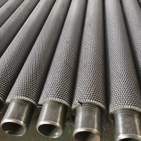
When selecting heat exchange components for industrial systems, engineers often weigh the trade-offs between Solid Finned Tubes and Serrated Finned Tubes. Both are manufactured using high-frequency welding, which ensures a strong metallurgical bond between the base tube and the fin. Yet the fin geometry creates distinct performance profiles. Which design delivers better thermal efficiency? How does the choice affect maintenance schedules and equipment lifespan? This article breaks down the material requirements, performance data, and real-world application patterns to help procurement and engineering teams make informed decisions.
Solid Finned Tubes vs Serrated Finned Tubes: Material Selection
The base tube and fin materials for both product types follow identical selection principles — they must withstand the operating temperature, pressure, and corrosion environment of the specific heat exchange application. The only material-related divergence arises from the serration process, which demands higher ductility from the fin strip to avoid cracking during the slitting operation. The table below compares material compatibility across common industrial grades.
| Component | High Frequency Welded Solid Finned Tubes | High Frequency Welded Serrated Finned Tubes | Key Selection Differences |
|---|---|---|---|
| Base Tube | Carbon steel – for low-temperature, non-corrosive services Stainless steel (304/316) – for corrosive or high-temperature duty Alloy steel (ND steel, 15CrMo) – for sulfuric acid dew point corrosion and high-pressure systems |
Identical material grades as solid-fin types; fully interchangeable with the same base tube specifications | No difference; both follow the same working-condition adaptation rules |
| Fins | Carbon steel – paired with anti-corrosion coatings (galvanizing, aluminizing) for cost-sensitive projects Stainless steel – for corrosive flue gas or chemical process streams Alloy steel (rare) – for extreme high-temperature and corrosive environments |
Carbon steel – requires higher ductility than standard grades to prevent edge cracking during slitting Stainless steel – needs higher-ductility plates (e.g., 304L, 316L) to ensure slot-edge integrity Heat-resistant alloys (310S) – for ultra-high-temperature serrated fin applications |
Serrated fins demand greater material ductility; solid fins have no extra ductility constraints |
| Welding Compatibility | Excellent material compatibility ensures consistent high-frequency weld quality; the bond is metallurgically sound across all common material pairs | The slotted fin structure reduces the contact area between fin and tube; welding parameters (current, pressure, speed) must be tightly controlled to avoid incomplete fusion at the slot roots | Serrated fins require more precise welding parameter control and more frequent quality checks |
Which material grade should you prioritize? For applications involving wet flue gas or acidic condensate, stainless steel base tubes paired with corrosion-resistant fins are strongly recommended. For dry, high-temperature gas streams, carbon steel with appropriate coatings often provides the best cost-performance balance. The serrated design does not alter the base material selection logic — it only adds a ductility requirement for the fin strip itself.
Solid Finned Tubes vs Serrated Finned Tubes: Performance Metrics
The structural difference between solid and serrated fins is the primary driver of performance divergence. Serrated fins introduce turbulence, which enhances convective heat transfer but also creates stress concentration points. The following table compares six key performance indicators under identical operating conditions.
| Performance Indicator | High Frequency Welded Solid Finned Tubes | High Frequency Welded Serrated Finned Tubes | Root Cause of Performance Differences |
|---|---|---|---|
| Heat Exchange Efficiency | Moderate – smooth fin surfaces encourage laminar boundary layers; heat transfer coefficient typically 30–50 W/(m²·K) at equivalent surface area | High – slots disrupt the laminar boundary layer and induce local turbulence; heat transfer coefficient reaches 45–70 W/(m²·K), 20%–40% higher than solid fins under the same conditions | Serrated geometry increases fluid mixing and reduces thermal resistance |
| Structural Strength & Impact Resistance | High – continuous fin surface without gaps, no stress concentration; withstands fluid velocities ≥30 m/s without deformation or fin detachment | Moderate – slotting reduces effective load-bearing area; stress concentration at slot edges limits maximum velocity to ≤20 m/s; high-velocity flows can cause fin flutter or cracking | Slotting compromises the structural continuity of the fin |
| Anti-Fouling Performance | Poor – smooth surfaces accumulate dust and scale readily; thick laminar boundary layers accelerate fouling; typical cleaning interval 1–3 months | Good – turbulent flow continuously scours fin surfaces, reducing deposit adhesion; cleaning interval extends to 3–6 months in most fouling services | Turbulent flow suppresses fouling layer formation |
| Corrosion Resistance | Uniform corrosion across the fin surface; no localized attack points; service life 5–8 years when using corrosion-resistant base tube grades (ND steel, 316 stainless) | Localized electrochemical corrosion can occur at slot edges, especially in wet or chloride-containing environments; anti-corrosion treatments (galvanizing, epoxy coating) are recommended; service life 4–6 years after proper treatment | Stress concentration and stagnant zones at slots accelerate localized corrosion |
| Manufacturing Cost | Lower – no slitting operation, higher production throughput; same-specification product costs 10%–15% less than serrated equivalents | Higher – slitting adds processing steps and material waste; tighter ductility requirements increase raw material costs; same-specification product costs 15%–25% more than solid-fin types | Slitting adds processing time, tooling wear, and material loss |
| Maintenance Difficulty | Easy – smooth surfaces can be cleaned quickly with brushing or compressed air; no special tools required | More complex – slot gaps trap fine particulates; high-pressure water jets or specialized rotary brushes are needed for thorough cleaning | Slot geometry creates blind spots that trap debris |
How do these metrics translate into real-world choices? If your system operates with clean gas at high velocity, solid fins offer better durability and lower cost. If you are recovering heat from dusty flue gas at moderate velocity, the efficiency and fouling resistance of serrated fins will likely justify the higher initial investment.
Solid Finned Tubes vs Serrated Finned Tubes: Selection Factors
The choice between solid and serrated fin designs depends on four primary operating parameters: fluid velocity, medium cleanliness, cost sensitivity, and maintenance capability. The decision matrix below summarizes the recommended selection for each scenario.
Fluid Velocity & Vibration
Solid Finned Tubes — High-velocity (>20 m/s) and high-vibration environments (boiler induced-draft outlets, furnace convection sections)
Serrated Finned Tubes — Low-velocity (<20 m/s) and low-vibration settings (waste heat recovery ducts, kiln tail gas systems)
Medium Cleanliness
Solid Finned Tubes — Clean media (steam, hot water, purified air, light hydrocarbons)
Serrated Finned Tubes — Dust-laden or scaling-prone media (flue gas, industrial wastewater, particle-laden air streams)
Cost Budget & Project Priority
Solid Finned Tubes — Cost-sensitive projects (civil heating, general industrial exchangers, budget-constrained retrofits)
Serrated Finned Tubes — Efficiency-priority projects (waste heat recovery, compact exchangers, energy-saving initiatives)
Maintenance Resources
Solid Finned Tubes — Limited maintenance resources, infrequent cleaning schedules, remote installation sites
Serrated Finned Tubes — Equipped with professional cleaning tools, regular maintenance crew, capability for in-depth cleaning
Why does velocity matter so much? At high gas velocities, the erosive force on fin edges becomes significant. Solid fins, being continuous and stress-free, resist erosion far better than serrated fins, whose slot edges are vulnerable to particle impact. Conversely, at low velocities where heat transfer is boundary-layer-limited, the turbulence from serrations provides a clear efficiency advantage.

Solid Finned Tubes vs Serrated Finned Tubes: Application Areas
The distinct performance characteristics of each fin type lead to well-defined application domains. Understanding where each design excels helps avoid costly mis-specification. The following breakdown covers the most common industrial use cases.
Where Solid Finned Tubes Deliver the Best Value
1. Boiler Air Preheaters & Economizers
- Operating conditions: Flue gas velocity 25–30 m/s, moderate dust loading, temperatures up to 400°C.
- Why solid fins work: The continuous fin structure withstands high-velocity gas scouring without fatigue failure. ND steel base tubes resist sulfuric acid dew point corrosion, making solid fins a proven solution for coal-fired and oil-fired boiler waste heat recovery.
2. Central Heating & HVAC Systems
- Operating conditions: Hot water or steam at moderate pressure, clean closed-loop medium, low particulate content.
- Why solid fins work: Cost-effective manufacturing and easy maintenance align with the large-scale requirements of civil heating projects. The smooth fin surfaces resist fouling from clean water, and the absence of slots eliminates debris-trapping points.
3. Petrochemical Low-Temperature Exchangers
- Operating conditions: Crude oil preheaters, light hydrocarbon condensers, clean oil/gas streams with stable flow.
- Why solid fins work: Smooth fin surfaces resist oil adhesion and are easy to clean during turnaround. The lower cost compared to serrated fins makes solid fins the preferred choice for non-critical heat exchange duties.
4. High-Vibration Metallurgical Applications
- Operating conditions: Blast furnace stove waste heat recovery, coke oven gas cooling — high vibration and thermal cycling.
- Why solid fins work: The absence of stress concentration points ensures long-term mechanical integrity under continuous vibration. Solid fins do not loosen or detach, even after years of thermal expansion and contraction cycles.
Where Serrated Finned Tubes Offer a Clear Advantage
1. Cement Kiln & Glass Furnace Waste Heat Recovery
- Operating conditions: Flue gas velocity below 15 m/s, high dust loading (alkali oxides, silica), temperatures 300–600°C.
- Why serrated fins excel: The turbulence induced by slots scours the fin surfaces, reducing dust accumulation. Higher heat transfer efficiency allows more compact heat exchanger designs, which is critical in space-limited retrofit projects.
2. Flue Gas Desulfurization (FGD) Heat Exchangers
- Operating conditions: Wet flue gas with sulfate droplets, high humidity, moderate temperature.
- Why serrated fins excel: The turbulent flow pattern reduces the adhesion of sulfate scale on fin surfaces. When paired with 316L stainless steel, serrated fins provide both fouling resistance and corrosion protection in the aggressive FGD environment.
3. Power Plant Air-Cooled Condensers
- Operating conditions: Limited footprint, high heat rejection requirements, ambient air as the cooling medium.
- Why serrated fins excel: The 20%–40% efficiency gain over solid fins translates to significantly smaller condenser footprint. For air-cooled condensers where space is at a premium, serrated fins provide the required thermal performance within the available area.
4. Coal Chemical & High-Viscosity Media
- Operating conditions: Coal tar, heavy oil, or wastewater containing suspended solids — high viscosity and fouling tendency.
- Why serrated fins excel: The continuous turbulent scouring prevents the formation of thick boundary layers that trap particulates. Serrated fins have proven effective in extending cleaning intervals from weeks to months in these challenging services.
Both High Frequency Welded Solid Finned Tubes and High Frequency Welded Serrated Finned Tubes have established track records across diverse industrial sectors. The optimal choice depends on a balanced assessment of fluid velocity, fouling potential, maintenance resources, and project economics. By matching the fin geometry to the specific operating conditions, engineers can maximize heat transfer efficiency while controlling lifecycle costs.