


In modern power plants, chemical refineries, and heavy processing facilities, heat rejection remains a foundational thermodynamic step. Historically, wet cooling towers dominated industrial cooling loops. However, growing water scarcity, strict environmental regulations on thermal effluent discharge, and rising water procurement costs have accelerated the shift toward dry cooling systems. The Air-Cooled Condenser (ACC) stands at the forefront of this dry-cooling transition, directly condensing process steam or vapor using ambient air as the cooling medium without consuming water.
At the mechanical core of every high-efficiency Air-Cooled Condenser lies the extended surface heat exchanger. Because ambient air possesses a significantly lower heat capacity and thermal conductivity than water, raw bare tubes cannot provide sufficient thermal duty within a realistic structural footprint. To compensate, high-performance extended surfaces—specifically spiral-wound finned tubes and single-row elliptical finned tubes—are essential to multiply the air-side heat transfer area by factors of 10 to 25. This technical analysis explores the engineering principles, design parameters, trade-offs, and tube selection criteria critical to optimizing Air-Cooled Condensers.
What Is an Air-Cooled Condenser and How Does It Work?
An Air-Cooled Condenser (ACC) is a direct dry cooling system designed to condense turbine exhaust steam or industrial hydrocarbon vapor directly inside finned tube bundles using forced or induced ambient air current. Unlike indirect dry systems that utilize an intermediate water loop, a direct ACC receives low-pressure steam directly from the steam turbine exhaust duct into large header manifolds.
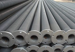
The operational process inside an Air-Cooled Condenser follows a precise thermodynamic sequence:
- Steam Distribution: Low-pressure exhaust steam flows through an overhead distribution duct (often termed the steam duct or trunk) situated above A-frame structural modules.
- Condensation inside Tubes: The steam enters inclined finned tube bundles, flowing downward. As colder ambient air is driven upward across the external finned surface by massive axial fans, latent heat of vaporization is transferred through the tube walls to the air. Steam condenses on the interior wall surface, creating a falling liquid condensate film.
- Condensate Collection and Degasification: Liquid condensate drains by gravity into condensate collectors (headers) at the base of the A-frame and is pumped back to the boiler feedwater system. Uncondensed gases and non-condensable steam are directed to a secondary condenser section (deaerating or counter-flow section) connected to a vacuum extraction system.
Key Technical Parameters and Standard Units in ACC Design
Engineering an efficient ACC requires balancing thermal performance, air-side pressure drop, and structural dimensions. Below are the primary design parameters that govern system sizing:
- Overall Heat Transfer Coefficient (U): Expressed in W/(m²·K) or Btu/(h·ft²·°F). Typical range for ACC air-side finned bundles is 25 to 45 W/(m²·K) (based on total external area), as air film resistance dominates the total thermal resistance. Final rating depends on project specification, engineer verification, and manufacturer testing.
- Air-Side Pressure Drop (ΔP_air): Expressed in Pascals (Pa) or inches of water column (in. WC). Typical range per bundle row is 30 to 120 Pa. Minimizing air-side pressure drop is critical to keeping fan auxiliary power consumption low.
- ITD (Initial Temperature Difference): Defined in Kelvin (K) or degrees Celsius (°C). It is the temperature difference between the entering saturated steam (T_sat) and the entering ambient dry-bulb air (T_air,in). Typical range is 15 K to 30 K. Lower ITD increases thermal efficiency but exponentially increases required bundle surface area.
- Air Face Velocity (v_face): Expressed in meters per second (m/s). Typical range is 1.5 to 3.0 m/s. Higher velocity improves thermal performance but increases fan noise and power draw.
Core Equations for ACC Heat Transfer and Pressure Drop Calculation
The thermal duty (Q) of an Air-Cooled Condenser module is governed by the fundamental heat exchanger equation:
Q = U × A_ext × ΔT_lm
Where:
- Q = Total thermal heat duty (W or Btu/h)
- U = Overall heat transfer coefficient based on total external surface area (W/(m²·K))
- A_ext = Total external extended surface area of the finned tubes (m²)
- ΔT_lm = Logarithmic Mean Temperature Difference (K or °C)
Because the extended fin area introduces thermal efficiency losses across the fin height, the effective overall heat transfer coefficient (U) is calculated by summing individual thermal resistances:
1 / U = (1 / h_int) × (A_ext / A_int) + R_wall + R_foul + 1 / (η_o × h_ext)
Where the variables are defined as follows:
- h_int = Internal steam-side condensation film coefficient (W/(m²·K))
- A_ext / A_int = Ratio of total external extended surface area to internal bare tube surface area (typical range: 12 to 25)
- R_wall = Convective wall thermal resistance of base tube (m²·K/W)
- R_foul = Internal/external fouling factor (m²·K/W), typical range 0.0001 to 0.0002 m²·K/W
- h_ext = External air-side convective heat transfer coefficient (W/(m²·K))
- η_o = Overall surface efficiency of the finned array (typical range: 0.80 to 0.95, dependent on fin geometry and material thermal conductivity)
Comparison of ACC Tube Geometries and Fin Types
Choosing the correct fin tube geometry directly impacts the footprint, structural load, thermal stability, and long-term operating cost of an Air-Cooled Condenser. The two primary tube architectures used in heavy dry cooling are Round High-Frequency Welded (HFW) / Extruded Finned Tubes and Elliptical Brazed Finned Tubes.
| Design Dimension | Round High-Frequency Welded (HFW) Solid Fin | Extruded Bimetallic Fin (Al/Steel) | Elliptical Tube with Steel/Al Fin |
|---|---|---|---|
| Base Tube Profile | Round (e.g., 25.4 mm to 38.1 mm OD) | Round (e.g., 25.4 mm to 38.1 mm OD) | Elliptical / Flat (e.g., 100 mm x 20 mm) |
| Fin Attachment | Continuous electric resistance welding | Rotary extrusion of aluminum sleeve over base tube | Brazing or mechanical hot-dip galvanizing |
| Air-Side Resistance (ΔP_air) | Moderate to high | Moderate | Lowest (aerodynamic profile) |
| Corrosion Protection | Requires external painting or galvanizing | 100% complete aluminum sheath coverage | Hot-dip galvanized (HDG) coating |
| Max Operating Temperature | Up to 400°C to 450°C | Up to 300°C | Up to 350°C |
| Structural Rigidity | High structural strength against mechanical vibration | High tube rigidity; fin protection against fouling | Requires precise bundle alignment |
| Capital Cost (CAPEX) | Cost-effective / Economical | Moderate to high | Higher initial investment |
Engineering Trade-offs in ACC Design
Designing an Air-Cooled Condenser involves balancing interconnected variables. Changing one core parameter creates trade-offs across capital cost (CAPEX) and operating expenditure (OPEX):
1. Fin Density (FPI) vs. Air-Side Fouling and Pressure Drop
Increasing fin density from 275 fins/m (7 FPI) to 394 fins/m (10 FPI) increases total surface area A_ext, reducing the physical footprint of the A-frame module. However, higher fin density increases air-side pressure drop (ΔP_air), requiring higher fan speed or motor horsepower. In dusty, arid, or agricultural environments, tightly packed fins collect airborne debris rapidly, degrading heat transfer performance and necessitating frequent high-pressure water washing.
2. Ambient Temperature Swings vs. Turbine Backpressure
Air-Cooled Condensers are sensitive to ambient dry-bulb temperature shifts. On hot summer days, entering air temperature rises, narrowing the ITD. To reject the required heat load Q, turbine backpressure must rise. Increased turbine backpressure decreases steam turbine thermal efficiency and power output. Engineers must balance fan sizing for peak ambient conditions against capital expenditure for larger steam ducting and structural steel.
3. Single-Row Elliptical Tubes vs. Multi-Row Round Finned Tubes
Multi-row round finned tube bundles (3 to 5 rows deep) offer lower upfront manufacturing costs. However, trailing tube rows suffer from reduced thermal driving force due to air preheating by leading rows. Single-row elliptical finned tube systems eliminate air preheating issues across rows and significantly reduce fan power draw, though at a higher initial equipment cost.
Technical Specifications, Materials, and International Standards
To guarantee structural integrity under deep vacuum conditions and resist atmospheric corrosion, materials and fabrication procedures must strictly adhere to recognized pressure vessel codes.
Note on Specification Ranges: Specific dimensions, materials, and testing standards provided below represent a typical range. Final material selection, wall thickness tolerances, and design margins must be confirmed according to project specifications, thermal calculations, and manufacturer datasheets.
Typical Material Specifications
- Base Tube Materials: Carbon steel (e.g., ASTM A106 Gr. B, ASTM A214, ASTM A179), Stainless Steel (e.g., ASTM A249 / A269 TP304L, TP316L for corrosive condensate environments).
- Fin Materials: Aluminum 1060 / 1100 (high thermal conductivity, approx. 200 W/(m·K)), Carbon Steel (for all-steel welded or hot-dip galvanized configurations).
- Tube Sheet and Header Plates: Heavy carbon steel plate (ASTM A516 Gr. 70) or matching alloy cladding.
Applicable Manufacturing and Design Standards
- API Standard 661 / ISO 13706: Petroleum, Petrochemical, and Natural Gas Industries — Air-Cooled Heat Exchangers.
- ASME Boiler and Pressure Vessel Code (BPVC) Section VIII, Division 1: Design and Construction Rules for Unfired Pressure Vessels.
- ASME PTC 30: Performance Test Code on Air-Cooled Heat Exchangers.
- HEI (Heat Exchange Institute): Standards for Air-Cooled Condensers.
Target Application Industries for Dry Air-Cooled Condensers
Direct Air-Cooled Condensers are specified across heavy process industries where water conservation, rapid site deployment, or zero liquid discharge (ZLD) mandates apply:
- Thermal Power Generation: Supercritical coal-fired, combined-cycle gas turbine (CCGT), and biomass power plants located in arid regions.
- Waste-to-Energy (WtE) Facilities: Municipal solid waste combustion plants requiring robust condensate heat rejection.
- Concentrated Solar Power (CSP): Parabolic trough and solar tower installations built in high-solar-irradiance desert locations lacking industrial water supplies.
- Chemical and Petrochemical Processing: Hydrocarbon fractionator overhead condensers and steam turbine drive exhaust loops where process fluid separation is critical.
- Geothermal Power Plants: Binary cycle and direct steam geothermal stations operating in ecologically sensitive regions.
Selection and Sizing Guide for Engineers and Procurement Managers
When specifying finned tubes for Air-Cooled Condenser construction or retubing projects, thermal design teams should evaluate the following criteria:
- Determine Ambient Environmental Conditions: Assess peak dry-bulb ambient temperature, elevation above sea level, wind rose profile, and ambient particulate/dust levels.
- Evaluate Corrosion and Atmospheric Threat Level: For marine or heavily industrial zones, specify extruded aluminum finned tubes or hot-dip galvanized steel tubes to prevent galvanic corrosion at the fin-tube interface. Alternative solutions like elliptical fin tubes provide low air resistance while offering robust zinc coating protection.
- Analyze Thermal Expansion and Vacuum Stability: Ensure base tube wall thickness meets full vacuum (100% vacuum / collapse pressure) at operating steam temperature according to ASME BPVC Sec VIII Div 1 calculations.
- Assess Maintenance and Cleaning Requirements: High-dust regions favor lower fin density and rigid fin attachment (such as extruded or high-frequency welded fins) that can withstand high-pressure water jet washing (100 to 150 bar) without fin flattening.
Quality Control and Testing Standards for ACC Finned Tubes
To ensure long service life under thermal cycling, continuous vacuum pressure, and wind loads, finned tube manufacturing requires strict quality assurance steps:
- Fin Bonding Integrity Test (Pull-off Test): Measures the mechanical bond strength between the fin root and base tube wall to prevent contact resistance growth over decades of service.
- Hydrostatic Testing: Each base tube undergoes hydrostatic testing per ASTM standards (typically 1.5 times design pressure) prior to or following finning.
- Pneumatic / Vacuum Leak Testing: Helium mass spectrometer leak testing or underwater pneumatic testing on completed tube bundles to ensure zero air ingress into vacuum steam headers.
- Dimensional Verification: Ultrasonic wall thickness measurement, fin pitch (FPI) verification, and total tube straightness control (typical tolerance within 1.0 mm per meter).
- Coating Thickness Test: For hot-dip galvanized tubes, zinc coating weight and thickness are verified according to ISO 1461 / ASTM A123 standards.
Packaging and International Shipping Requirements
Finned tubes engineered for large Air-Cooled Condensers feature delicate high-surface area fins vulnerable to mechanical impact during export transport. Professional packing standards include:
- Structural Steel Crated Bundles: Tubes are packed into heavy wooden or structural steel transport frames fitted with custom-contoured HDPE or rubber tube support spacers. These spacers keep adjacent fin tips separated, preventing fin crushing during sea freight transit.
- End Cap Protection: Plastic bevel protectors or push-in caps applied to plain tube ends protect weld preparations and internal surfaces from moisture and debris.
- Desiccant and Vapor Corrosion Inhibitors (VCI): Bundles are wrapped in heavy-duty VCI stretch film or vacuum-sealed aluminum barrier foil to prevent atmospheric oxidation during ocean transport.
Frequently Asked Questions (FAQ)
1. What is the primary difference between direct and indirect Air-Cooled Condensers?
In a direct Air-Cooled Condenser, steam turbine exhaust flows directly inside the finned tubes and condenses against ambient air. In an indirect dry cooling system, steam is condensed in a conventional surface condenser using circulating water; that heated water is then pumped to a dry cooling tower where air cools the water inside finned coils. Direct systems eliminate intermediate heat exchanger losses and water pumps, making them more common for thermal power generation.
2. Why are fins necessary on tubes used in Air-Cooled Condensers?
The convective heat transfer coefficient of air (approx. 30 to 80 W/(m²·K)) is far lower than that of condensing steam inside the tube (approx. 5,000 to 10,000 W/(m²·K)). Adding external fins increases the air-side surface area by up to 20 times, balancing the thermal resistance on both sides and reducing the physical size of the condenser unit.
3. How does ambient air temperature affect Air-Cooled Condenser performance?
Because dry cooling relies on the ambient dry-bulb temperature, high summer temperatures lower the Initial Temperature Difference (ITD). This lowers steam condensation capacity and raises steam turbine exhaust backpressure, slightly reducing net plant power output compared to cooler winter conditions.
4. What causes thermal contact resistance in finned tubes, and how is it avoided?
Thermal contact resistance occurs when a gap forms between the fin root and the outer base tube wall due to thermal expansion differences or corrosion. This gap disrupts heat flow. Utilizing continuously high-frequency welded fins or bimetallic extruded aluminum fins ensures a seamless metallurgical bond or mechanical interference fit, preventing contact resistance growth over time.
5. How are Air-Cooled Condenser finned tubes cleaned of ambient dust and debris?
ACC bundle external surfaces are periodically cleaned using automated high-pressure water wash rigs mounted above or below the A-frame bays. Extruded aluminum and high-frequency welded steel fins provide the mechanical strength necessary to withstand high-pressure water sprays without bending or flattening.
6. What fin density (FPI) is ideal for an Air-Cooled Condenser?
Typical fin density ranges from 236 to 394 fins per meter (6 to 10 fins per inch). Lower fin densities are specified in environments prone to heavy atmospheric dust, sand, or airborne debris, while higher densities are used in clean industrial areas to maximize heat transfer per module.
Optimize Your Dry Cooling System with High-Performance Finned Tubes
Looking for reliable high-frequency welded or extruded finned tubes for your next Air-Cooled Condenser project, retrofitting, or retubing program? Lordfintube delivers precision-engineered heat transfer solutions manufactured to strict international pressure vessel standards.
Request a Quote