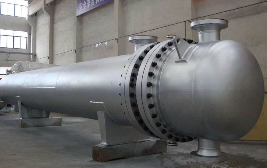
How to design a shell and tube heat exchanger?
How to design a shell and tube heat exchanger?
The design calculation of a shell and tube heat exchanger involves several steps. Heres a general overview of the process:
- Determine the heat duty: Start by determining the required heat transfer rate or heat duty (Q) of the heat exchanger. This can be based on the specific application or process requirements.
- Determine the fluid properties: Identify the properties of the hot fluid (inlet temperature, outlet temperature, flow rate, specific heat capacity, and density) and the cold fluid (same properties) involved in the heat exchange process.
- Choose the shell and tube arrangement: Select a suitable shell and tube arrangement based on factors such as pressure drop limitations, fouling tendencies, ease of maintenance, and overall efficiency. Common arrangements include the fixed tube sheet, U-tube, and floating head designs.
- Determine the overall heat transfer coefficient (U): The overall heat transfer coefficient represents the efficiency of the heat exchanger in transferring heat between the hot and cold fluids. It is calculated using a combination of the individual film coefficients for the fluids inside and outside the tubes, as well as the thermal resistance of the tube wall.
- Determine the tube side heat transfer area: Calculate the required heat transfer area on the tube side using the formula:
A = Q / (U × ΔTm)
where A is the heat transfer area, Q is the heat duty, U is the overall heat transfer coefficient, and ΔTm is the logarithmic mean temperature difference (LMTD). The LMTD depends on the temperature difference between the hot and cold fluids at various points along the length of the heat exchanger. - Select the tube size and layout: Determine the tube diameter and length based on factors such as pressure drop constraints, fluid velocity limitations, and fouling considerations. Also, decide on the tube layout pattern, such as triangular or square pitch.
- Check for tube side flow velocity: Verify that the tube side flow velocity falls within acceptable limits to prevent excessive pressure drop or flow issues. The recommended range is typically 1-3 m/s for liquid flows and 10-20 m/s for gas flows.
- Check for tube side pressure drop: Calculate the pressure drop on the tube side using empirical correlations or detailed flow analysis. Ensure that the pressure drop is within acceptable limits based on the system requirements.
- Determine the shell side heat transfer area: Calculate the required shell side heat transfer area based on the tube side heat transfer area, fouling factors, and overall heat transfer coefficient.
- Select the shell size and layout: Choose a suitable shell diameter and length, considering factors such as pressure drop limitations, available space, and manufacturing considerations.
- Check for shell side flow velocity: Verify that the shell side flow velocity falls within acceptable limits to prevent excessive pressure drop or flow issues. The recommended range is typically 0.1-0.3 m/s for liquid flows and 0.2-1 m/s for gas flows.
- Check for shell side pressure drop: Calculate the pressure drop on the shell side using empirical correlations or detailed flow analysis. Ensure that the pressure drop is within acceptable limits based on the system requirements.
- Design the tube sheets, baffles, and supports: Design the tube sheets, baffles, and support structures to withstand the pressure, temperature, and mechanical stresses encountered during operation.
- Perform iterative calculations: Iteratively adjust the tube and shell dimensions, as well as other design parameters, to meet the desired heat transfer area, pressure drop, and other performance requirements.
Its important to note that the design calculation of a shell and tube heat exchanger can be complex and may require detailed knowledge of heat transfer principles, fluid mechanics, and thermal engineering. Consider consulting specialized literature, engineering codes, or seeking assistance.
Shell and tube heat exchanger design parameters
What are the typical design parameters that engineers need to specify during the design phase? The table below summarizes key parameters and their typical ranges or values for shell and tube heat exchangers in industrial applications.
| Parameter | Typical Range / Value | Remarks |
|---|---|---|
| Tube outside diameter | 15.9 mm (5/8″) – 31.8 mm (1¼″) | 19.1 mm (3/4″) and 25.4 mm (1″) are most common |
| Tube wall thickness | 1.2 mm – 3.0 mm (BWG 16 – 10) | Depends on pressure and corrosion allowance |
| Tube length | 1.5 m – 12 m | Standard lengths: 6 m, 9 m, 12 m |
| Tube pitch (triangular) | 1.25 × OD – 1.5 × OD | Triangular pitch offers higher heat transfer area |
| Tube pitch (square) | 1.25 × OD – 1.5 × OD | Square pitch allows easier mechanical cleaning |
| Shell inside diameter | 200 mm – 2500 mm | Determined by tube count and layout |
| Baffle spacing | 0.2 × Dshell – 1.0 × Dshell | Closer spacing increases heat transfer but raises pressure drop |
| Baffle cut (segment height) | 15% – 45% of shell diameter | Typical cut: 25% – 35% |
| Tube side velocity (liquid) | 1.0 – 3.0 m/s | Higher velocity improves heat transfer, increases erosion risk |
| Shell side velocity (liquid) | 0.1 – 0.3 m/s | Lower than tube side due to larger flow area |
| Fouling resistance (typical) | 0.0001 – 0.001 m²·K/W | Varies with fluid type and operating conditions |
Shell and tube heat exchanger type comparison
Which shell and tube heat exchanger design is right for your application? The choice between fixed tube sheet, U-tube, and floating head designs depends on thermal, mechanical, and maintenance requirements. The comparison below highlights the key differences.
| Design Type | Advantages | Disadvantages | Typical Applications |
|---|---|---|---|
| Fixed Tube Sheet | Simple construction, low cost, no internal gaskets | Cannot accommodate thermal expansion; shell side cleaning difficult | Clean services, moderate temperature differences |
| U-Tube | Allows thermal expansion; tube bundle removable; good for high pressures | Harder to clean tubes internally; lower tube count per shell diameter | High temperature differentials, thermal shock, fouling fluids |
| Floating Head | Accommodates thermal expansion; both sides can be cleaned; tube bundle removable | Higher cost; more complex construction; internal gaskets require maintenance | Severe fouling, large temperature differences, frequent cleaning |
Shell and tube heat exchanger material selection
How do you choose the right materials for a shell and tube heat exchanger? Material selection affects corrosion resistance, strength, thermal conductivity, and cost. The following guidelines help narrow down the options based on operating conditions.
Tube Materials
- Carbon steel (SA-179, SA-214): General service, moderate temperatures, non-corrosive fluids.
- Stainless steel (TP304, TP316, TP321): Corrosive environments, high temperatures, food/chemical processing.
- Copper alloys (Admiralty, Cu-Ni 90/10): Excellent thermal conductivity, seawater and brine services.
- Titanium & Hastelloy: Severe corrosion, seawater, acidic media, high-cost specialty applications.
Shell & Header Materials
- Carbon steel (SA-516, SA-285): Standard shells for moderate pressures and temperatures.
- Stainless steel: When shell side fluid is corrosive or product purity is critical.
- Clad materials: Carbon steel with stainless or alloy cladding for cost-effective corrosion resistance.
- Cast iron / Ductile iron: Low-pressure, non-critical applications.
Why does material matter? Beyond corrosion, thermal expansion compatibility between tube and shell materials must be checked. Differential expansion can cause tube-sheet joint failure or tube buckling. Always consult ASME Section VIII and TEMA standards for material allowable stresses and design rules.
Shell and tube heat exchanger design questions