


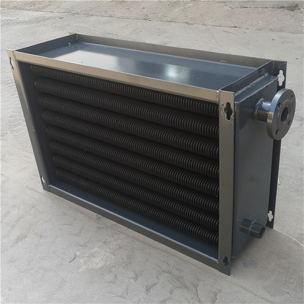
Products Description
Custom-built finned tube evaporators and evaporator coils for refrigeration, HVAC, chemical, petrochemical, and power applications. Tube diameter, fin pitch, circuiting, materials, and design code are configured to the process datasheet — not forced into a catalogue size. A finned tube evaporator is a heat exchanger in which a refrigerant or process fluid evaporates inside tubes while the extended fin surface on the outside absorbs heat from air, water, or another process stream. The finned surface compensates for the low heat-transfer coefficient on the gas or air side. By extending the effective area — typically 8 to 20 times the bare tube area — a finned tube evaporator achieves a compact footprint at far lower material cost than an equivalent bare-tube bundle. Depending on the service, the unit may be a shell-and-tube evaporator with finned tubes, an air-cooled evaporator coil, or a flooded or dry-expansion coil in a refrigeration or process duty. A finned tube evaporator coil is the coil assembly — tubes, fins, return bends, headers, and refrigerant distributor — through which refrigerant evaporates while air or a secondary fluid is cooled across the finned face. In most HVAC and refrigeration systems the coil is the component that actually absorbs heat from the conditioned space or process stream. The coil is defined by its face area, number of tube rows, fin pitch, circuiting, and refrigerant distribution. Those four parameters, more than tube material alone, determine capacity, air-side pressure drop, and defrost behaviour. Mechanical expansion, hydraulic expansion, or tension winding bonds the fin to the tube. A consistent bond limits contact resistance and keeps capacity stable through thermal cycling. Circuit count and distributor selection control refrigerant velocity, pressure drop, and feed balance. Poor circuiting causes uneven frost, hot spots, and capacity loss. Face area sets the face velocity; row depth sets the air-side contact time. Deep coils raise capacity but increase air-side pressure drop and fan power. Denser fins add surface but trap frost and dust. Wider pitches are standard for low-temperature, frosted, or particulate-laden duty. Brazed or welded headers, with brazed or welded U-bends, are selected to suit the refrigerant, pressure rating, and site repair capability. Galvanised, stainless, or coated steel casings with drain pans and lifting points, sized to fit the air handling unit or cooler enclosure. Selection tip: frost forms fastest at the coil face nearest the entering air. If the application runs below roughly 0 °C coil surface temperature, specify a wider fin pitch and confirm the defrost strategy before the coil is built. The table below shows typical ranges. Final values are confirmed against the process datasheet, the applicable design code, and the mechanical design calculation for each unit. Note: The values above are indicative engineering ranges, not a guarantee of performance. Each evaporator and coil is thermally rated and mechanically designed to the actual project conditions. Gas processing, dew-point control, stabiliser reboilers, and low-temperature separation trains. Distillation reboilers, concentrators, process chillers, and solvent recovery. Condenser air removal, flue gas cooling, and auxiliary cooling circuits. Air-handling unit coils, flooded chillers, cold rooms, blast freezers, and industrial refrigeration. Brine chilling, hygienic process cooling, and controlled-temperature evaporation. Solvent recovery, clean-room cooling, and controlled evaporation duty. Brine and vapour-side duty in thermal processes and water treatment. Corrosion-resistant coils for coastal, offshore, and shipboard installations. Selection starts with the duty, not the geometry: define the heat load, the temperature programme, the flow rates, and the allowable pressure drop first, then size the surface and choose the fin configuration. Third-party inspection by a nominated agency can be arranged at defined hold points when the project specification requires it. A finned tube evaporator carries extended surface on the outside of the tubes, so it delivers the same heat duty with fewer tubes and a smaller shell or casing. Bare tube units are simpler to clean and are often preferred for heavily fouling or high-temperature service. It is the coil that absorbs heat in an air-handling unit, chiller, cold room, blast freezer, or industrial refrigeration system. Refrigerant evaporates inside the tubes while air or a secondary fluid is cooled as it passes across the finned face. Select the widest fin pitch that still meets the thermal duty. Dense fins raise the surface area but increase air-side pressure drop and make cleaning harder. For dust-laden, frosting, or fouling streams, a wider pitch is usually the more economical long-term choice. Row depth is set by the required capacity and the allowable air-side pressure drop. Adding rows increases capacity but also fan power and coil depth. For most comfort-cooling coils the practical range is 2 to 8 rows; deeper coils are used where the duty demands it. For chloride-bearing or acidic streams, stainless steel, duplex, titanium, or cupronickel tubes are common selections. The fin material is chosen separately because it contacts a different medium. Final selection depends on the fluid analysis, temperature, and required corrosion allowance. Hot-gas defrost is common in industrial refrigeration; electric defrost is used where hot gas is unavailable. Off-cycle defrost suits light frosting duty. Fin pitch and circuit layout are adjusted to suit the chosen method. Yes. Units can be mechanically designed to ASME BPVC Section VIII Div. 1, EN 13445, PED 2014/68/EU, GB/T 151, TEMA, or API 660 as specified. Please state the design code, design pressure and temperature, and the required documentation package in your enquiry. Provide the heat load, both-side flow rates, inlet and outlet temperatures, allowable pressure drops, fluid or refrigerant type, design pressure and temperature, design code, connection sizes, and any space or weight limits. Drawings of the available envelope help shorten the review cycle. Lead time depends on material availability, bundle or coil size, and the extent of third-party inspection. A firm schedule is confirmed after the technical review and material release. Yes. Replacement bundles and coils can be manufactured to the original drawing or to reverse-engineered dimensions when drawings are not available. Send us your process datasheet — heat load, temperatures, flow rates, allowable pressure drop, refrigerant or fluid, materials, and design code — and our engineering team will review the thermal and mechanical design and return a technical proposal with a firm quotation. Please include the design pressure and temperature, fluid composition, defrost or cleaning requirements, and any inspection or documentation requirements so that the offer reflects the full scope of supply.Finned Tube Evaporator & Evaporator Coil
What Is a Finned Tube Evaporator?
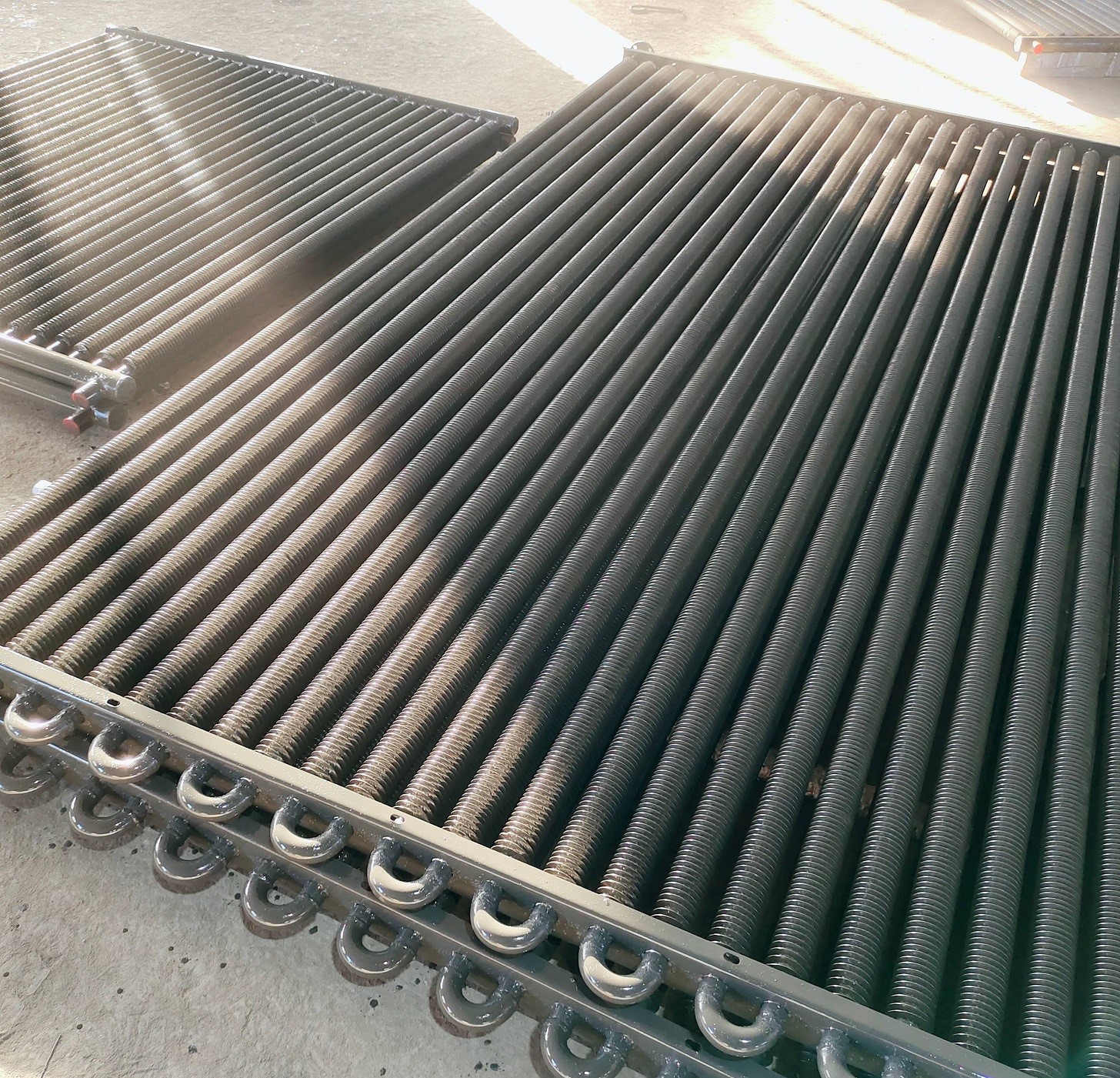
What Is a Finned Tube Evaporator Coil?
Coil Construction — What Determines Performance
Tube & Fin Bond
Circuiting & Refrigerant Distribution
Face Area & Row Depth
Fin Pitch
Headers & Return Bends
Coil Casing
Common Evaporator Coil Configurations
Coil Type
Typical Tube / Fin Material
Typical Service
Copper tube / aluminium fin
Copper tube, aluminium fin
General HVAC, commercial refrigeration, chillers
Aluminium tube / aluminium fin
All-aluminium
Lightweight coils, ammonia and CO₂ systems where compatible
Copper tube / copper fin
Copper tube, copper fin
Corrosive atmospheres, marine and coastal installations
Stainless steel tube / SS fin
SS 304 / 316L
Food, pharmaceutical, hygienic and wash-down areas
Cupronickel or titanium tube
CuNi 90/10, 70/30, titanium
Brine, seawater, high-chloride duty
Carbon steel tube / CS or SS fin
SA179, SA192, SS fins
Process and refinery evaporator service
Refrigerants and Operating Envelope
Core Advantages of Our Finned Tube Evaporators and Coils
Technical Specifications
Parameter
Typical Range / Options
Tube outside diameter
12.7 mm to 38.1 mm (0.5 in to 1.5 in)
Tube wall thickness
0.9 mm to 3.0 mm, depending on pressure and corrosion allowance
Tube length
Up to approximately 12 m, subject to shipping and handling limits
Fin height
6 mm to 20 mm
Fin pitch
4 to 12 fins per inch (approx. 157 to 472 fins per metre); 6 to 14 FPI available for coil duty
Fin thickness
0.3 mm to 1.2 mm
Fin type
Helically wound (L-foot, KL, overlap), tension wound, extruded, embedded, or plate-fin
Coil rows
2 to 12 rows, typical range
Coil face velocity
Typically 1.5 to 3.5 m/s, confirmed against allowable carry-over and pressure drop
Tube side design pressure
Typically up to 10 MPa, depending on material, wall thickness, and code
Design temperature
Approximately −60 °C to +400 °C, limited by the selected materials and joint design
Design codes
ASME BPVC Section VIII Div. 1, TEMA, API 660, EN 13445, PED 2014/68/EU, GB/T 151 — as specified
Connection types
Flanged, welded, threaded, brazed, or grooved per project specification
Surface finish
As-welded, pickled and passivated, painted, or coated on request
Materials and Standards
Tube materials
Fin materials
Applicable standards
Application Industries
Oil & Gas
Chemical & Petrochemical
Power Generation
HVAC & Refrigeration
Food & Beverage
Pharmaceutical
Desalination & Water
Marine & Offshore
How to Select a Finned Tube Evaporator or Evaporator Coil
Fin Type Comparison
Fin Type
Typical Use
Considerations
Helically wound L-foot
Air-side heating and cooling at moderate temperature
Good contact at moderate temperatures; not suited to severe thermal cycling
KL / overlap wound
Higher-temperature air-side duty
Better fin retention under expansion; slightly higher cost
Extruded
Corrosive or high-vibration service
Fin is integral with the tube surface; limited to compatible tube materials
Embedded / grooved
High-temperature and high-cycling duty
Strong mechanical bond; requires thicker tube wall at the groove
Plate fin / expanded coil
HVAC and refrigeration coil assemblies
High surface density; requires consistent expansion for bond quality
Evaporator vs. Condenser Coil — Quick Reference
Characteristic
Evaporator Coil
Condenser Coil
Heat flow
Absorbs heat from the process stream
Rejects heat to the ambient or cooling medium
Refrigerant state change
Liquid to vapour
Vapour to liquid
Moisture behaviour
Condensate forms; drain pan required
Generally dry operation
Frost risk
Yes, below roughly 0 °C coil surface
No
Typical fin pitch
6 to 12 FPI, wider for low temperature
10 to 14 FPI
Cleaning access
Critical — fouling and bio-film risk
Important, mainly dust and debris
Quality Control and Inspection
Packaging and Shipping
Frequently Asked Questions
What is the difference between a finned tube evaporator and a bare tube evaporator?
What is a finned tube evaporator coil used for?
How do I choose the right fin pitch?
How many coil rows do I need?
Which materials are suitable for corrosive duty?
What defrost method should be used for low-temperature coils?
Can the evaporator be designed to a specific code?
What information is needed to prepare a quotation?
What is the typical lead time?
Do you provide replacement finned tube bundles and coils?
Request a Finned Tube Evaporator or Coil Quotation