


Lord Fin Tube-Finned tube increase the heat transfer
Finned Tube Increase the Heat Transfer
Finned tubes, also called fin tubes or finned coils, are an engineering response to a simple physical problem: a bare tube wall offers far too little surface for the duty demanded of it. This page breaks down the mechanisms, the measured performance, and the design trade-offs behind the way a Finned tube increase the heat transfer in air-side, gas-side and liquid-side service, and explains how fin geometry and material choice change the outcome on a real project.
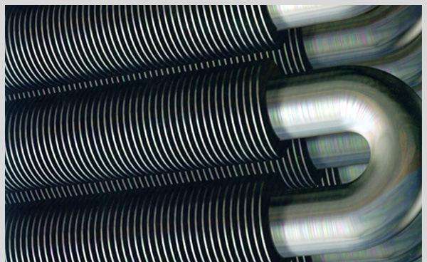
Advanced finned tube design showing fin geometry for maximum heat transfer efficiency
Finned Tubes Technical Insight
Finned tubes can increase heat transfer efficiency by 200-400% compared to plain tubes of the same base area, making them indispensable in applications where space constraints or high thermal performance requirements exist.
Which Mechanisms Make Finned Tube Increase the Heat Transfer
Increased Surface Area (Primary Enhancement)
The primary function of fins is to dramatically increase the effective surface area available for heat transfer. By attaching extended surfaces to the outer diameter of the tube, the surface area expands by factors ranging from 3x to 15x compared to a plain tube, depending on fin geometry and density.
Boundary Layer Disruption & Convective Enhancement
Fins strategically disrupt the thermal boundary layer that naturally forms on heat transfer surfaces. This boundary layer acts as an insulating barrier, and by disturbing it, fins reduce thermal resistance and increase the convective heat transfer coefficient by 25-50% in typical applications.
Thermal Resistance Reduction
Fins effectively distribute thermal energy across a larger surface area, reducing the temperature gradient between the tube wall and the surrounding fluid. This optimization of the thermal pathway decreases overall thermal resistance in the system.
Turbulence Induction
In forced convection applications, fins create controlled turbulence that enhances fluid mixing. This turbulence brings fresh, cooler fluid into direct contact with the heated surfaces, significantly improving heat transfer rates.
What Measured Data Shows About Finned Tube Increase the Heat Transfer
Numbers taken from published exchanger tests make the comparison easier to read than theory alone. A bare tube and a finned tube of the same outside diameter and the same wall thickness move very different amounts of energy once the fin count rises.
| Parameter | Plain Tube | Low-Fin Tube (5:1 Ratio) | High-Fin Tube (15:1 Ratio) | Performance Improvement |
|---|---|---|---|---|
| Surface Area Ratio | 1.0 | 5.2 | 15.8 | Up to 15.8x increase |
| Heat Transfer Coefficient (W/m²K) | 45-60 | 85-120 | 110-160 | Up to 267% improvement |
| Overall Heat Transfer (U-value) | 35-50 | 65-95 | 90-140 | Up to 280% increase |
| Pressure Drop Increase | Baseline | 15-25% | 40-60% | Trade-off consideration |
| Space Efficiency | 1.0 | 3.5-4.2 | 7.8-9.5 | Up to 9.5x more compact |
Three values tend to decide whether a finned design wins the order. They are listed below because they are the numbers most often quoted back by procurement teams when a quotation is challenged.
Surface Area Increase
Typical surface area enhancement with finned tubes compared to plain tubes
Heat Transfer Improvement
Increase in heat transfer efficiency with optimized finned tubes
Compactness Factor
Reduction in required space for equivalent heat transfer capacity
Why Fin Geometry Decides How Much Finned Tube Increase the Heat Transfer
Two finned tubes can share the same outside diameter and still behave nothing alike. Height, density, thickness and fin pattern each push performance in a different direction, and each one carries a penalty somewhere else in the system.
| Fin Parameter | Typical Range | Impact on Performance | Application Considerations |
|---|---|---|---|
| Fin Height | 3-25 mm | Higher fins increase surface area but may reduce fin efficiency | Balanced based on fluid properties and space constraints |
| Fin Density | 2-12 fins per cm | Higher density increases surface area but raises pressure drop | Optimized based on allowable pressure drop |
| Fin Thickness | 0.2-1.5 mm | Thicker fins improve durability but reduce number of fins | Selected based on mechanical and thermal requirements |
| Fin Type | Helical, Longitudinal, Segmented | Different flow patterns and heat transfer characteristics | Matched to application (gas/liquid, clean/fouling fluids) |
Material Selection Impact
The thermal conductivity of fin materials significantly impacts overall performance. Common materials include:
- Aluminum: High thermal conductivity (205 W/mK), lightweight, cost-effective for air-side applications
- Copper: Excellent thermal conductivity (385 W/mK), good corrosion resistance, higher cost
- Carbon Steel: Moderate conductivity (50 W/mK), high strength, used in high-temperature applications
- Stainless Steel: Lower conductivity (15 W/mK), excellent corrosion resistance, used in harsh environments
Fin Efficiency and the Point of Diminishing Return
A taller fin does not stay as hot as the tube wall it sits on, so its tip contributes less than its root. Once fin efficiency drops below roughly 70%, adding more height buys very little extra duty while still adding weight, cost and pressure loss. Suppliers who quote fin height alone, without fin efficiency, are usually quoting a shape rather than a result.
Where Finned Tube Increase the Heat Transfer Delivers Results
Finned tubes find extensive application across multiple industries where efficient heat transfer is critical:
HVAC Systems
In air conditioning and refrigeration systems, finned tubes enable compact heat exchangers that efficiently transfer heat between refrigerant and air, with typical fin densities of 3-8 fins per centimeter.
Power Generation
In power plants, finned tubes are used in economizers, air preheaters, and heat recovery steam generators (HRSGs) to maximize energy recovery from flue gases, improving overall plant efficiency by 3-8%.
Process Industries
Chemical, petrochemical, and oil refining industries utilize finned tubes in process heaters, coolers, and reactors where precise temperature control and compact heat exchange are essential.
Which Service Conditions Weaken the Gains
Fins pay for themselves only while the surface stays clean and the fan or pump keeps moving fluid across it. Dust bridging between close fins, condensate holding on the air side, and fouling layers on the inside of the tube all push the real duty back toward bare-tube values. Where the air stream carries lint, soot or salt spray, wider fin spacing and a lower fin count often hold their performance longer than a dense, high-area design that fouls within one season. This is why the same nominal finned tube can be the right answer in one plant and the wrong answer in the next one.
Questions Engineers Ask About Finned Tube Increase the Heat Transfer
How much can a finned tube actually raise heat transfer over a bare tube?
On the gas or air side, where the film coefficient is low, a well-designed finned tube commonly moves 200% to 400% more heat than a bare tube of the same base area. On the liquid side the gain is much smaller, because the outside film is no longer the limiting resistance and the tube wall itself dominates.
Does a higher fin count always improve performance?
No. Past a certain density the boundary layers of adjacent fins merge and the added surface stops doing useful work, while pressure drop keeps climbing. There is an optimum density for every air velocity and every fin height.
What is the penalty for adding fins?
Pressure drop on the finned side typically rises 15-25% for a low-fin tube and 40-60% for a dense high-fin tube. That means a larger fan, a bigger pump, or more pumping power, and it has to be counted against the heat transfer gained.
Why do two suppliers quote different duties for the same finned tube?
Usually because one is quoting bare-tube area and the other is quoting total extended surface, or because one applied a fin efficiency correction and the other did not. Ask for the fin efficiency, the reference area, and the fouling allowance before comparing the two numbers.
Finned tubes work through four effects that reinforce each other: more surface, a thinner boundary layer, a shorter thermal path, and better fluid mixing. Fin geometry and material set the ceiling on how far those effects can be pushed, while the operating environment decides how much of that ceiling survives in year three. Matching the two is what separates a finned tube that keeps its duty from one that only looks good on the data sheet.