


Advantages of Finned Tube Heat Exchanger
Air is a poor carrier of heat. On the gas side of a bare tube bundle the film coefficient usually sits somewhere between 30 and 90 W/m²·K, while steam condensing inside the same tube reaches 6,000 to 12,000 W/m²·K. That mismatch is the whole reason finned surfaces exist, and it is why the Advantages of Finned Tube Heat Exchanger become so visible in air heating, drying and flue gas recovery work. Same steel, same steam, plus a few thousand thin sheets of metal.
What follows is written for the person who has to sign off on the purchase order: which gains are real, the conditions under which they disappear, and what to confirm with a supplier before the enquiry turns into a contract.
Advantages of Finned Tube Heat Exchanger in Air Heating Duties
Finned tubes earn their place by adding surface without adding footprint. A bare 25 mm tube presents roughly 0.08 m² of air-side area per metre of length. The same tube wound with aluminium fins 16 mm high at eight fins per inch jumps to about 0.8 m² — close to ten times the area, with almost no change to the depth or width of the bundle. Since Q = U × A × ΔT, that single change can turn a box that barely works into one that carries a real heating load.
There is a second benefit that buyers notice later: finning gives the designer somewhere to go other than raising air velocity. Fan power rises roughly with the cube of velocity, so a coil that compensates for thin surface area by pushing air harder will see its electricity bill climb far faster than its duty. A finned bundle can be sized at lower face velocity, lower pressure drop and a quieter fan for the same heat output.
Why the Air-Side Film Coefficient Matters More Than the Tube Side
Think of the thermal path as a chain of resistances. In a steam coil, the condensing side offers roughly 6,000 to 12,000 W/m²·K. The air side offers 30 to 90. A 1 mm carbon steel wall contributes a figure near 5,000 W/m²·K. The weakest link sets the pace, so thickening the wall or switching to a more conductive metal achieves very little. Enlarging the air-side surface shifts the balance of resistances directly, and that is where most of the practical gain comes from.
What Fin Efficiency Does to the Numbers
An aluminium fin does not behave like an infinite plate. Heat travelling outward along the fin loses temperature as it goes, so the tip contributes less than the root. Fin efficiency captures this, and for 15 to 16 mm aluminium fins it typically lands between 0.88 and 0.95. Push fin height past roughly 20 mm and efficiency falls while aluminium consumption per metre climbs. Beyond a certain point, extra fin height costs more than it returns.
How Fin Geometry Affects the Advantages of Finned Tube Heat Exchanger
Fin pitch, fin height, transverse pitch and row count are not independent dials. Turn one and the others move with it.
| Change made | Air-side heat transfer | Air-side pressure drop | Fan power | Practical note |
|---|---|---|---|---|
| Raise face velocity | Rises | Rises | Rises steeply | Returns diminish; beyond roughly 3 m/s the pressure penalty outpaces the heat gained |
| Widen fin pitch | Falls slightly | Falls | Falls | Overall duty often peaks near 1.8–2.0 mm for condensers and 1.9–2.1 mm for evaporators |
| Increase fin height | Rises | Rises | Rises | Average coefficient per unit area drops; fin efficiency and material use both suffer |
| Add more tube rows | Rises | Rises | Rises | Back rows see a smaller temperature difference, so each additional row earns less than the last |
| Switch staggered to in-line | Falls | Falls | Falls | Worth considering where dust makes cleaning a routine job |
Fin density per metre of tube, tube diameter and the transverse and longitudinal pitches all feed into the same balance. A coil that looks generous on total area can still underperform if the air cannot reach the inner rows, or if the pressure drop forces a smaller fan than the duty needs.
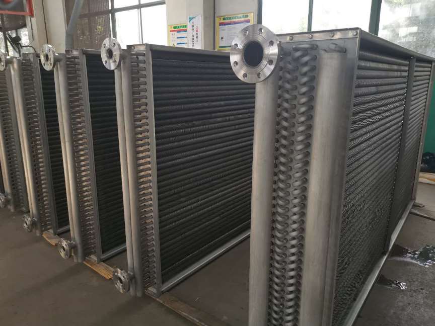
Advantages of Finned Tube Heat Exchanger in Waste Heat Recovery
Hot flue gas is where finned tubes do their best work, and also where they are most often misapplied. Gas leaving a boiler or furnace at 250 to 400 °C carries a large mass flow and a large quantity of recoverable heat. Adding fins on the gas side means the same recovery fits into a smaller casing, and a pure counterflow arrangement becomes easier to achieve without complicated headers.
The trouble sits at the cold end. Gas from sulphur-bearing fuel has an acid dew point somewhere between 120 and 160 °C. Once the outer tube surface drops below that figure, sulphuric acid condenses onto the fins, carbon steel turns to rust, and leaks follow. Oversizing the finned area so the gas leaves colder makes the problem worse, not better.
The practical answer is adjustable area: decide at design stage which rows will see the coldest gas, and make those rows removable, or build them from stainless or ND steel fins while the rest stay carbon steel. With that arrangement the stack temperature can be pulled down toward 150 °C without surrendering the recovery that a straight dew point margin would cost.
Advantages of Finned Tube Heat Exchanger with Steam and Thermal Oil
Steam and thermal oil both release heat at close to constant temperature, which suits a finned bundle well. Because the condensing temperature barely shifts along the tube, pushing air across the outside in pure counterflow needs no elaborate circuiting — the air outlet can approach the saturation temperature, with the gap set by the heat transfer itself rather than by the layout.
A finned bundle also tolerates vertical or inclined mounting, which matters in retrofit work where a horizontal duct simply will not fit. Evaporating and condensing sections can be sized independently against their own duty, since the two sides are not structurally interlocked. When a single tube fails through wear, corrosion or overheating, only that tube is lost and the two media never mix — a property that counts for a great deal when either fluid is flammable or aggressive. It is one of the reasons a finned tube heat exchanger gets written into duties where a plate unit would be a liability.
Where the Advantages of Finned Tube Heat Exchanger Have Limits
Taking finned tubes on faith is a common way for projects to go wrong. There are several situations where the sums do not work out:
- Dusty or sticky gas. Fin gaps act as collection slots. Where the exhaust carries fibre, oil mist or tacky particulate, a pitch below 6 mm will blind over quickly. Widen the pitch, or take the solids out upstream.
- High temperature. Wound aluminium fins begin to fail above 200 to 210 °C. Beyond that, either move to steel fins or accept a shorter service life.
- Cleaning difficulty. The finned section resists mechanical cleaning. A bare tube can be scraped or augered; a finned bundle usually needs compressed air, steam or chemical washing, and that has to be scheduled rather than hoped for.
- Weight and depth. Finned bundles add mass and depth. The casing grows with them, and on some jobs that eats back part of the saving.
Advantages of Finned Tube Heat Exchanger in a Drying Line Project
The situation. A textile finishing plant ran three stenter frames, each exhausting about 3,000 m³/h of hot air at 165 °C. Make-up air entered at roughly 20 °C and the plant wanted it preheated to at least 85 °C using the same thermal oil loop that already fed the drying ovens — oil supply at 260 °C, return at 240 °C. The existing bare tube coil could only lift the make-up air to about 55 °C and pulled the oil return down further than the boiler liked.
What was specified.
- Fin type: steel fins wound onto steel tubes. Aluminium was ruled out because the oil supply at 260 °C sits well above the 200 to 210 °C ceiling where the fin-to-tube bond starts to degrade.
- Fin height held at 12 to 13 mm rather than 16 mm. Steel conducts heat at roughly a quarter of the rate of aluminium, so taller fins would have lost efficiency without earning it back.
- Tube diameter 25 mm, wall thickness 2 mm, carbon steel.
- Fin pitch 4 mm — the exhaust was relatively clean, but the extra clearance left room for periodic air cleaning.
- Four rows, staggered, face velocity held at 2.6 m/s to keep fan power within the existing motor rating.
What the plant measured afterwards.
- Make-up air temperature rose from 20 °C to approximately 85 °C.
- Recovered duty settled near 65 kW per frame, about 195 kW across the three lines.
- Air-side pressure drop landed around 210 Pa, comfortably inside the existing fan curve.
- Oil return temperature improved by roughly 11 °C, which cut the number of boiler firing cycles per shift.
- At 6,000 operating hours a year, the recovered heat represents a little over 1.1 GWh of avoided fuel input.
| Item to confirm | What to ask the supplier | Why it decides the outcome |
|---|---|---|
| Fin type and bonding method | Wound, extruded or bimetallic? Is a pull-off figure available? | Contact resistance decides how much of the quoted surface actually performs |
| Fin pitch and tube pitches | Exact millimetre values, not the word standard | Sets pressure drop, blockage risk and the cleaning method that will be needed |
| Tube wall thickness and grade | Carbon steel, stainless or ND steel, and how thick? | Drives dew point corrosion behaviour and expected service life |
| Design point | Face velocity, inlet air temperature and mass flow at that point | The same bundle performs very differently once the duty moves away from the quoted case |
| Air-side pressure drop | Pa value at the specified flow, not at a nominal one | Determines fan selection and the running cost over the life of the unit |
| Shop testing | Hydrostatic test, air tightness, fin appearance checks | Cheaper to find a fault in the workshop than on site during a shutdown |
Questions About the Advantages of Finned Tube Heat Exchanger
Do finned tubes always move more heat than bare tubes?
In most heating and cooling duties they do, but the honest test is not the total surface figure. Ask which coil delivers more heat at the same face velocity and the same outlet temperature. A deep finned bundle looks impressive on paper, yet the back rows see air that has already been warmed by the front rows, so row six contributes far less than row two. Doubling finned area never doubles performance.
Which fin material lasts longest in a flue gas stream?
It depends on temperature and on what the gas carries. Carbon steel is the wrong choice where sulphur-bearing fuel is burned and the outer surface may fall below the acid dew point, no matter how dense the fins are. Switch to stainless or ND steel fins in the cold end. Carbon steel remains acceptable above 250 °C when wall temperature stays clear of the dew point and chlorides are absent. Aluminium suits clean air up to roughly 200 °C.
How can a buyer check whether the fin-to-tube bond is sound?
Ask for pull-off or bond strength figures at quotation stage, and verify by sampling on delivery. A transverse section through an extruded bimetallic tube shows whether the aluminium has fully gripped the steel. On a tension-wound fin, a light twist by hand should not let the fin rotate independently of the tube. A poor bond shows up later as heat transfer below the calculated value.
Can a finned tube heat exchanger be cleaned in place?
Compressed air, low-pressure steam or a mild chemical wash all work. A high-pressure water jet will fold the fins flat, and stiff brushes push dirt deeper into the gap. Where oil mist or fibre is present in the exhaust, specify a wider fin pitch from the start rather than planning to scrub the bundle later.
What fin spacing should be specified for a dusty exhaust?
A rough starting point is 2 to 3 mm for clean air, 4 to 6 mm for lightly laden gas, and 8 mm or more once fibre, soot or sticky particles appear. Another rule of thumb: if the largest common particle is bigger than about one third of the clear gap between fins, blockage is only a matter of time. Adding a filter or cyclone ahead of the coil is usually cheaper than widening the fin pitch.