


Inner Finned Tubes: Core Industrial Components for High-Efficiency Heat Transfer
In the fields of industrial heat exchange, HVAC and refrigeration, energy and chemical engineering, heat exchange tubes serve as fundamental components for heat transfer. Their performance directly determines the energy efficiency, overall size, and operational stability of heat exchange equipment. Compared with traditional smooth round tubes, inner finned tubes adopt specialized inner-wall reinforced structures, effectively solving the bottlenecks of low heat transfer efficiency and extensive laminar heat transfer dead zones. As core components of modern high-efficiency and energy-saving heat exchangers, they are widely applied in high-precision, high-load, and compact heat transfer scenarios and play a vital role in the upgrading of industrial heat exchange technology.
1. Definition and Structural Classification of Inner Finned Tubes
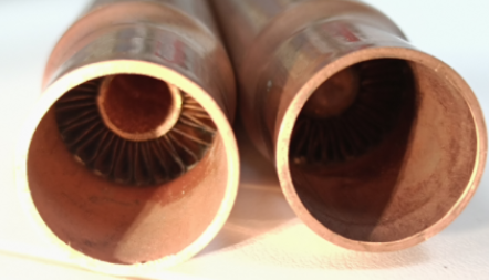
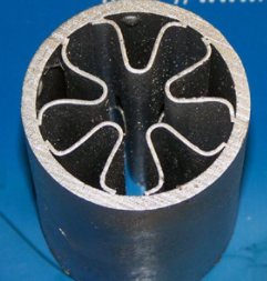
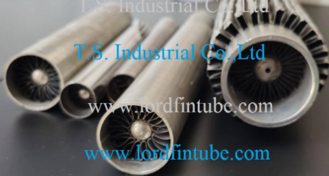
An inner finned tube is a special heat transfer tube designed to intensify tube-side heat transfer. Integral fins are formed on the inner wall of seamless carbon steel, copper, and stainless steel base tubes through precision rolling, extrusion, and other forming processes. Unlike outer finned tubes that enhance external heat transfer, inner finned tubes focus on improving the heat transfer efficiency of internal fluid, compensating for the limitations of smooth tubes including insufficient heat transfer area and single fluid flow pattern.
According to the geometric morphology and structure of inner fins, industrial inner finned tubes are mainly divided into three categories for differentiated working conditions:
Straight inner finned
Uniformly distributed axial straight fins. Regular structure, low fluid resistance, mature manufacturing processes. Suitable for conventional heat transfer scenarios with stable flow velocity and strict pressure drop requirements. Widely used in HVAC and general refrigeration equipment.
Spiral inner finned
Spirally arranged inner fins along the tube axis. The spiral structure forces internal fluid to generate swirling turbulence, destroying the laminar boundary layer and significantly enhancing heat transfer. Better comprehensive thermal performance than straight fins, applied in chemical cooling, oil-gas heat exchange, etc.
Corrugated & special-shaped
Upgraded high-efficiency products equipped with continuous corrugated and irregular concave-convex fin structures. Some advanced models feature central flow disturbance structures, eliminating internal heat transfer dead zones. Highly adaptable to high-temperature, high-viscosity, and low-flow fluid conditions.
In addition to structural morphology, the forming process is a key factor determining the structural strength, thermal performance, and working condition adaptability of inner finned tubes. Commercially available industrial inner finned tubes adopt homogeneous integral forming technology, where the base tube and fins are made of the same material and integrally molded without splicing. This structure eliminates contact thermal resistance and ensures reliable and stable heat transfer performance. The two mainstream industrial forming methods are rolling molding and extrusion molding, which match different fin structures with distinct technical characteristics.
Based on structural design and forming technology, inner finned tubes can be customized with different base materials according to working temperature, pressure, fluid medium, and anti-corrosion requirements. The mainstream materials include copper alloy, stainless steel, carbon steel, and aluminum alloy. The core characteristics and applicable scenarios of each material are listed in the table below:
| Tube Material | Core Advantages | Disadvantages | Applicable Working Conditions and Applications |
|---|---|---|---|
| Copper/Copper Alloy | Extremely high thermal conductivity, excellent plasticity for precision fin rolling, optimal heat transfer performance, and good air tightness | Moderate pressure and wear resistance, relatively high cost, poor resistance to strong corrosion | Suitable for precision heat transfer scenarios with low pressure and clean mediums. Widely used in central air conditioning, heat pump units, refrigeration evaporators and condensers to improve thermal efficiency and reduce system energy consumption. |
| Stainless Steel (304/316L) | High temperature resistance, oxidation resistance, corrosion resistance, high structural strength, excellent pressure bearing capacity, and long service life | Relatively low thermal conductivity, difficult processing, and high manufacturing cost | Adaptable to harsh working conditions with high temperature, high pressure, and acid-base corrosion. Mainly applied in chemical fluid heat exchange, oil-gas cooling, industrial waste heat recovery, and generator cooling systems. |
| Carbon Steel Seamless Tube | High mechanical strength, excellent pressure resistance, high cost performance, and convenient processing and forming | Ordinary thermal conductivity, prone to oxidation and rusting, poor corrosion resistance | Applicable to high-pressure industrial conditions without strong corrosion. Commonly used in large-scale industrial waste heat equipment, air compressor coolers, and hydraulic oil cooling devices. |
| Aluminum Alloy | Light weight, high cost performance, good thermal conductivity, and outstanding lightweight advantages | Poor high-temperature and pressure resistance, low structural strength, vulnerable to acid and alkali corrosion | Suitable for normal-temperature, low-pressure, and clean medium conditions. Applied in lightweight civil HVAC equipment, precision instrument cooling, vehicle-mounted heat exchange devices, and small new energy thermal management systems. |
2. Heat Transfer Mechanism: Dual Enhancement to Break Thermal Bottlenecks
The low heat transfer efficiency of smooth tubes stems from the stable laminar boundary layer formed on the inner wall, where heat transfer relies merely on low-speed thermal conduction, resulting in massive heat transfer blind zones and low thermal coefficients. Inner finned tubes achieve a substantial improvement in heat transfer performance through a dual enhancement mechanism: expanded heat transfer area and turbulent flow disturbance.
On the one hand, densely arranged inner fins greatly expand the effective tube-side heat transfer area. Compared with smooth tubes of the same specification, the heat transfer area of inner finned tubes increases by more than 50%, enlarging the contact and heat transfer dimension between fluid and tube wall and improving the basic heat transfer capacity.
On the other hand, the fin structure actively disturbs the fluid flow state. The fluid is continuously cut and disturbed when flowing through the fins, breaking the stable laminar flow and forming uniform turbulence. The turbulent fluid continuously scours the boundary layer, eliminates laminar heat transfer dead zones, and significantly reduces thermal resistance. Experimental data show that inner finned tubes increase evaporation heat transfer coefficients by 50%–100% and condensation heat transfer coefficients by 100%–200%, presenting remarkable thermal enhancement effects.
Furthermore, the integrally formed fins are tightly bonded with the base tube without contact gaps, minimizing contact thermal resistance. Heat is rapidly conducted from the base tube to the entire fin area to realize full-range efficient heat conduction, avoiding heat loss of assembled structures and ensuring long-term stable thermal performance.
3. Core Technical Advantages of Inner Finned Tubes
3.1 High Heat Transfer Efficiency and Significant Energy Saving
Benefiting from expanded heat transfer area and turbulent flow disturbance, inner finned tubes completely overcome the low-efficiency defect of smooth tubes. Under identical working conditions and equipment volume, they deliver far higher heat transfer efficiency. To meet the same heat load requirement, they reduce fluid flow rate and equipment energy consumption, providing prominent long-term energy-saving benefits and complying with industrial energy conservation and low-carbon development trends.
3.2 Compact Structure and Lightweight Adaptability
The superior thermal performance eliminates the need for large-scale tube arrangements. Under the same heat transfer capacity, inner finned tubes effectively reduce the overall volume and floor area of heat exchangers. They are especially suitable for space-limited scenarios such as air compressor coolers, vehicle-mounted heat exchange equipment, and micro-channel heat exchangers, supporting miniaturization and lightweight upgrading of thermal equipment.
3.3 Strong Working Condition Adaptability and Operational Stability
By optimizing geometric parameters including fin height, fin pitch, and fin thickness, the tubes achieve an optimal balance between heat transfer efficiency and flow pressure drop. They are adaptable to low-viscosity clean mediums such as water and air, as well as medium and high-viscosity fluids including oil and chemical solutions. The integral forming structure features high rigidity, deformation resistance, and wear resistance. With corrosion-resistant materials, it adapts to complex high-temperature and acid-base conditions, realizing a longer service life than ordinary heat transfer tubes.
3.4 Anti-Fouling Performance and Low Maintenance Cost
The continuous turbulent scouring effect inside the tube restricts the adhesion and accumulation of impurities and scale on the inner wall, greatly reducing the risk of tube fouling and blockage. It lowers the frequency of equipment shutdown and cleaning, cuts operational and maintenance costs, and ensures long-term efficient and stable operation of heat exchange systems.
4. Conclusion
Through structural innovation, inner finned tubes break through the performance limitations of traditional heat transfer tubes. With the comprehensive advantages of high thermal efficiency, energy saving, compact structure, and stable operation, they have become essential basic components for modern heat exchange technology.