


Integral Finned Tubes for Cement Plant
Integral Finned Tubes for Cement Plant
Integral Finned Tubes for Cement Plant: What Are They?
The Integral Finned Tubes for Cement Plant is most advanced finned tube, which produced by hot rolled from thick-walled seamless steel tubes. Integral finned tubes supplier provides high heat transfer efficiency for waste heat exchanger recovery in cement plants. The thick-walled seamless steel pipe is rolled into the integral finned tube in one process to achieve designed tube thickness, fin height, fin pitch by rolling blades distributed in the circumferential direction at 120° while heated the steel pipe to 900-950℃ by medium frequency induction from 2000HZ to 2500HZ. The finned tube is integral and with the smooth joint surface.
Integral Finned Tubes vs High-Frequency Welded Tubes
The most widely used finned tubes are made by a high-frequency welding method, they are widely used in waste heat recovery in electric power, metallurgy, cement industry and petrochemical industry. The high-frequency welding finned tube is the production method by finned the steel pipe by steel trip with a certain pressure by using the skin effect and the proximity effect of the high-frequency current to heat the outer surface of the steel strip to the plastic or melting state. Compared with inlaying, brazing finned tube, high-frequency welding finned tube is more advanced in terms of product quality with up to 95% fin weldability, productivity and automation.
Integral Finned Tubes: Advantages
1. Excellent heat exchange efficiency - The fin and the tube are integrated into one structure, completely eliminating the contact thermal resistance of other forms of finned steel tube which cannot be overcome due to the two-body structure of the fin and the tube, and the longitudinal section of the fin has a trapezoidal structure, so the maximum improvement of fin heat exchange efficiency can be made.
2. Heat exchange surface extended - The heat transfer coefficient of the tube bundle is 2 times bigger than the high-frequency welded finned tubes with the same tube wall thickness under the same working conditions.
3. Excellent reliability - As the fin and the pipe are integrated into one structure results suitable working high temperature and harsh working environment where the circumstance of fin break off from the tube is easy occurred.
Integral Finned Tubes: Applications in Cement Industry
Widely used in power station boilers, waste heat boilers, ships, steel, petroleum, chemical, refrigeration, HVAC and other industrial and civil heat exchange fields.
Integral Finned Tubes: Features
1. Long service life, up to three times that of a high-frequency finned tube.
2. Smooth joint surface eliminates ash and slag accumulation, which is easily produced by the finned tube at the root of the fin.
3. Integrated fin and tube as an integral whole, due to the hot rolling process, which improves metal structure density, yield strength, tensile strength, and wear resistance.
4. Superior pressure bearing capacity - The integral finned tube is three times stronger in pressure bearing than other finned tubes with the same wall thickness.
5. Excellent pressure bearing capacity - The integral finned tube is more than three times stronger in pressure bearing than other finned tubes with the same wall thickness.
6. Excellent wear resistance solves the problem of high convective heating surface of coal-fired boiler due to high wind speed and high ash concentration. (especially circulating fluidized bed boilers).
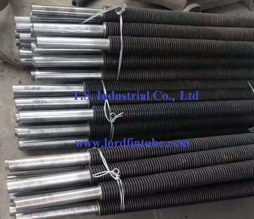
Integral Finned Tubes for Cement Plant
Integral Finned Tubes: Technical Specifications
Understanding the precise technical parameters of Integral Finned Tubes is essential for cement plant engineers when selecting the right heat exchanger components. The table below summarizes key specifications for standard integral finned tubes used in waste heat recovery applications.
| Parameter | Value Range / Details |
|---|---|
| Tube Outer Diameter | 25 mm – 76 mm (custom sizes available) |
| Tube Wall Thickness | 2.5 mm – 6.0 mm (depending on pressure rating) |
| Fin Height | 8 mm – 16 mm |
| Fin Pitch | 3 mm – 10 mm |
| Fin Root Thickness | 0.8 mm – 1.5 mm |
| Base Tube Material | Carbon steel, alloy steel (SA 210, SA 213, 12CrMoV, 15CrMo), stainless steel (304, 316L) |
| Maximum Working Temperature | Up to 600°C (depending on material grade) |
| Manufacturing Standard | ASTM A179, A213, ASME Section VIII, DIN 17175, GB/T 24593 |
| Fin Surface Treatment | Anti-corrosion coating, aluminizing, or as-rolled |
Typical technical specifications for integral finned tubes used in cement plant waste heat recovery systems.
Integral Finned Tubes: Comparison with Other Types
Which finned tube type delivers the best balance of performance, durability, and cost for cement plant applications? The table below compares Integral Finned Tubes against other common finned tube variants across key criteria.
| Criteria | Integral Finned Tubes | High-Frequency Welded | Embedded (G-type) | Brazed |
|---|---|---|---|---|
| Heat Transfer Efficiency | ★★★★★ (highest, no contact resistance) | ★★★★☆ | ★★★☆☆ | ★★★☆☆ |
| Pressure Bearing Capacity | ★★★★★ (3× stronger than welded) | ★★★☆☆ | ★★☆☆☆ | ★★☆☆☆ |
| Service Life | ★★★★★ (up to 3× longer) | ★★★☆☆ | ★★☆☆☆ | ★★☆☆☆ |
| Wear Resistance | ★★★★★ (hot-rolled structure) | ★★★☆☆ | ★★☆☆☆ | ★★☆☆☆ |
| Ash & Slag Accumulation | ★★★★★ (smooth root, minimal buildup) | ★★★☆☆ | ★★☆☆☆ | ★★★☆☆ |
| Manufacturing Cost | ★★★★☆ (higher initial investment) | ★★★★★ (most cost-effective) | ★★★☆☆ | ★★☆☆☆ |
| High-Temperature Performance | ★★★★★ (up to 600°C) | ★★★★☆ | ★★★☆☆ | ★★★☆☆ |
Performance comparison of integral finned tubes versus other finned tube technologies for cement plant environments.
Why Choose Integral Finned Tubes for Cement Plants?
Why do leading cement producers increasingly specify Integral Finned Tubes for their waste heat recovery systems? The answer lies in the unique combination of operational benefits that directly address the challenges of cement plant environments.
▷ Elimination of contact thermal resistance – The one-piece construction ensures that heat flows without interruption from the tube wall to the fin, maximizing thermal conductivity and overall heat transfer coefficient.
▷ Superior resistance to thermal fatigue – The hot-rolling process refines the grain structure of the metal, enhancing resistance to cyclic thermal stresses common in cement plant heat exchangers.
▷ Reduced maintenance frequency – The smooth fin root and integrated design minimize ash bridging and slag deposition, cutting cleaning downtime by up to 40% compared to welded finned tubes.
▷ Longer replacement cycles – With a service life three times that of conventional welded tubes, cement plants achieve lower lifecycle costs and improved plant availability.
How Do Integral Finned Tubes Enhance Heat Recovery Efficiency?
How does the integral design translate into measurable performance gains for cement plant waste heat recovery? The mechanism centers on three key factors:
- Zero interfacial resistance – Unlike welded or embedded tubes, integral finned tubes have no interface between the fin and the base tube, so heat transfer occurs without any thermal barrier. This yields a heat transfer coefficient that is 2 times higher than high-frequency welded tubes with identical wall thickness under the same operating conditions.
- Optimized fin geometry – The trapezoidal longitudinal fin profile promotes better airflow and reduces boundary layer buildup, allowing more effective heat extraction from flue gases in cement plant kiln exhaust systems.
- Improved surface area utilization – The rolling process creates a dense, uniform fin structure that maximizes the extended surface area per unit length, delivering up to 30% more heat exchange surface compared to embedded fin designs of similar outer dimensions.
These factors collectively enable cement plants to recover more waste heat and convert it into usable energy, reducing fuel consumption and lowering carbon emissions per ton of clinker produced.
Which Factors Influence the Performance of Integral Finned Tubes?
Which variables should cement plant engineers monitor to ensure optimal performance of Integral Finned Tubes in their heat recovery systems? The following factors have the most significant impact:
- Flue gas velocity and particulate loading – Higher velocities improve convective heat transfer but increase erosion risk. Integral finned tubes, with their superior wear resistance, withstand velocities up to 15 m/s in high-ash environments without significant degradation.
- Inlet gas temperature – Operating within the materials maximum temperature limit (typically 600°C for alloy steel grades) ensures long-term structural integrity. Exceeding this threshold can accelerate oxidation and reduce fin life.
- Fin pitch selection – Tighter fin pitches (e.g., 3–4 mm) provide more surface area but are more prone to fouling. Wider pitches (6–10 mm) offer better self-cleaning characteristics in dusty cement plant flue gases. The optimal pitch depends on the specific ash composition and gas velocity.
- Base tube wall thickness – Thicker walls provide greater pressure capacity and corrosion allowance but reduce overall thermal conductance. Engineers must balance pressure requirements with heat transfer targets based on system design parameters.
- Installation and tube-to-tubesheet joint quality – Proper welding or rolling of the tube ends into the tubesheet is critical to prevent leakage and maintain structural rigidity under thermal cycling conditions.
Regular inspection of fin condition, tube wall thickness, and deposit buildup is recommended to sustain peak performance throughout the equipments service life.
Integral Finned Tubes for Cement Plant: Operational Best Practices
To maximize the return on investment when deploying Integral Finned Tubes in cement plant heat exchangers, operators should adopt the following practices:
- Monitor differential pressure – An increase in pressure drop across the finned tube bundle often indicates fouling or ash accumulation. Scheduled cleaning using soot blowers or water washing (where applicable) restores heat transfer efficiency.
- Control gas velocity distribution – Uneven flow across the tube bundle can cause localized overheating or erosion. Baffle design and inlet duct geometry should be optimized to ensure uniform gas distribution.
- Maintain proper tube support – Adequate support spacing prevents vibration-induced fatigue, particularly in long-span tube runs common in large cement plant waste heat boilers.
- Document performance trends – Tracking outlet gas temperature, heat recovery rate, and tube metal temperature over time helps identify degradation early and schedule maintenance proactively.
When these practices are followed, cement plants consistently report heat recovery improvements of 12–18% over systems using conventional finned tube designs, along with extended equipment life and reduced unplanned downtime.