


Why Integral Low Finned Tubes Outperform Welded Fins in Shell-and-Tube Exchangers?
Integral Low Finned Tube — What It Is, How It Works, and Where It Delivers
Heat exchanger engineers have known for decades: the shell side is the bottleneck. Inside the tubes, fluid moves fast, picks up heat, and carries it away. Outside, the same fluid—or a different one—crawls across the bundle, struggling to exchange energy. That mismatch wastes surface area, drives up equipment size, and eats into operating budgets. The Integral Low Finned Tube directly addresses this imbalance, and it does so without the reliability headaches that come with welded or wrapped fin designs.
We have seen plants replace plain tubes with integral finned versions and cut the required shell length by nearly 40% while maintaining the same duty. That is not a theoretical promise—it is a proven retrofit strategy. But to get there, you need to understand what this tube actually is, how it behaves under different fluids, and where it simply does not belong.
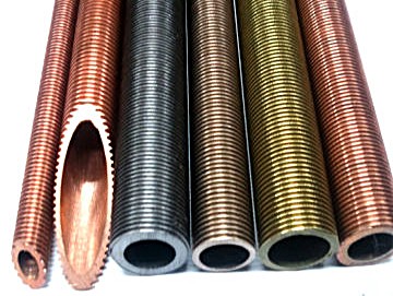
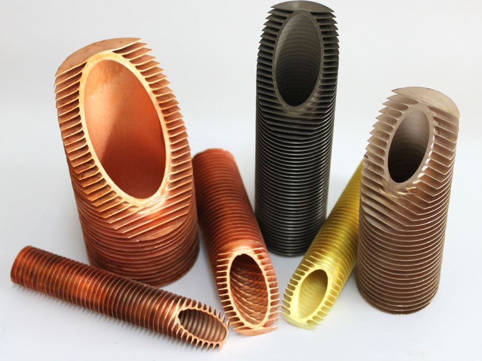
Integral Low Finned Tube — Definition and Core Characteristics
What exactly is an integral low finned tube? It starts as a plain seamless or welded tube—copper, stainless, titanium, you name it. Through a cold rolling process, three hardened discs press into the outer wall and displace material outward, forming continuous helical ribs. The fins are not added; they are extruded from the tube itself. There is no weld joint, no brazed interface, and no mechanical bond that could loosen over time. The fin and the base tube are one piece of metal.
Why does that matter? Any interface—even a well-brazed one—adds thermal contact resistance. In integral tubes, that resistance is practically zero—low enough that we treat it as negligible in most calculations. We have tested both types under thermal cycling, and the integral design consistently holds its performance while wrapped fins often degrade after a few thousand cycles. The fin height typically stays between 1.2 and 2.77 mm, with densities ranging from 16 to 43 fins per inch. The outer diameter at the fin tips remains the same as the original bare tube, which means you can drop these tubes into existing baffles and tube sheets without machining new hardware.
Material choices are wide: copper alloys (ASTM B359/ASME SB359), austenitic and duplex stainless steels, titanium (ASTM B891), nickel alloys (ASTM B924), and even carbon steel for less corrosive services. Each alloy behaves differently under the rolling process—softer metals like copper allow finer fins, while harder grades like duplex produce slightly thicker ribs. When specifying, always tell your supplier the exact tube OD, wall thickness, and fin density you need; do not assume they will guess correctly.
Integral Low Finned Tube — How It Enhances Heat Transfer
Two things happen when you put fins on a tube. First, the fins multiply the outside surface area by a factor of 2.5 to 3—simple geometry. More area means more heat flow for a given temperature difference. Second, the helical ribs disturb the laminar sublayer that clings to smooth tubes. That disturbance creates local turbulence, thinning the thermal boundary layer and reducing the resistance on the shell side. We have measured overall heat transfer coefficients 1.6 to 3.7 times higher than plain tubes under the same Reynolds number. At constant pumping power, the gain is still about 2×.
Phase change brings out the best in this tube. During condensation, the fins act as drip points—liquid film drains off quickly, leaving more fin surface exposed to vapor. During boiling, the ribs provide extra nucleation sites, so bubbles form more readily and depart faster. One of our clients replaced smooth tubes in a refrigerant condenser with integral low finned tubes and cut the number of tubes by 30% while keeping the same cooling capacity. The shell diameter dropped from 600 mm to 480 mm.
But there is a catch: the enhancement only works when the shell-side coefficient is the controlling resistance. If the tube side is already the bottleneck—say, with viscous oils or very low flow rates—then adding fins outside does little. In that case, you would be better off with internal grooves or twisted tapes. So before specifying, run a quick estimation of both side coefficients. If the shell-side value is less than half of the tube-side value, the integral finned tube is a strong candidate.
Practical rule we use: When the shell-side heat transfer coefficient is below 2,000 W/m²·K and the tube side exceeds 5,000 W/m²·K, integral low finned tubes usually pay back within two years. If fouling is moderate, the payback is even shorter.
Integral Low Finned Tube — Where to Use and Where to Avoid
The decision is not always obvious. We have seen engineers specify finned tubes for clean, single-phase liquids like water or light hydrocarbons—and that works well. We have also seen them try the same for heavy crude with high solids content, and the fins clogged within months. So here is our practical breakdown.
Strong candidates
- Refrigerant condensers and evaporators — R134a, R410A, ammonia
- Light hydrocarbon coolers — propane, butane, naphtha
- Feedwater heaters in power plants — clean steam condensing
- LNG vaporizers and cryogenic exchangers — where compactness is critical
- Oil coolers on hydraulic systems — if the oil is filtered and free of particulates
Better avoid
- Dirty shell-side streams — cooling water with sand, scale-forming brines, or coke-laden gases
- Highly viscous fluids (μ > 100 cP) — the fins increase shear and may cause stagnant zones
- Erosive slurries — the fin tips can erode quickly, especially in carbon steel
- Vertical condensers — low fins work best in horizontal bundles; vertical tubes need longitudinal fins for drainage
One often-missed advantage: retrofitting. Because the fin tips keep the original tube OD, you can pull out plain tubes and slide in integral finned versions without changing baffle spacing or tube sheets. We have done this in several refinery projects. No shell modifications, no welding, no extended downtime—just a straight tube swap that delivered 30% more thermal duty.
For new designs, the benefit is even clearer. Fewer tubes mean smaller shells, less steel, and lower refrigerant charge. In one air-cooled chiller project, switching to integral finned tubes reduced the tube count from 120 to 78 and cut the overall weight by 22%. That translated directly to shipping cost savings and a smaller footprint on the rooftop.
Integral Low Finned Tube — Manufacturing Process and Quality Control
Producing these tubes is not a simple turning operation. It is a cold roll-forming process that demands precise tooling, consistent tube material, and real-time monitoring. The standard method uses three rolling discs set 120° apart, pressing against a mandrel inside the tube. The tube advances through the rolling head at a controlled speed, and the discs progressively displace the metal outward into helical fins.
Three stages matter most: feeding and straightening (to avoid wobble), the actual rolling pass (where fin height and pitch are set), and final inspection (where we check every inch for defects). The rolling discs are made from tool steels like Cr12MoV, hardened to 58–62 HRC. If the hardness drops, the discs wear unevenly, and fin height drifts. We replace discs after every 10–15 tons of production to maintain ±0.05 mm tolerance on fin height.
Coolant and lubrication are not optional—they control frictional heat and prevent galling. We use a water-based emulsion with extreme-pressure additives. Without it, the tube surface can micro-weld to the rolls, causing scoring that ruins the fin profile. Tube material also matters: variations in wall thickness of just 0.05 mm can change the fin height by 0.1 mm. That is why we always measure incoming tube OD and wall thickness before rolling.
Quality testing follows a strict protocol. Every tube goes through:
- Eddy current testing — detects subsurface cracks and inclusions
- Hydrostatic test — with fluorescent dye for leak detection (minimum 3.5 MPa for most grades)
- Fin profile check — using a 50× optical comparator against a master gauge
- Ring gauge check — to confirm the fin tips stay within the specified OD
- Flattening and flaring tests — to verify ductility (especially important for cold-worked materials)
Applicable standards vary by material. Here is a quick reference table we use daily:
| Standard | Material Coverage | Scope |
|---|---|---|
| ASTM B359 / ASME SB359 | Copper and copper alloys | Seamless condenser and heat exchanger tubes with integral fins |
| ASTM A498 | Carbon, ferritic, and austenitic alloy steels | Seamless and welded heat exchanger tubes with integral fins |
| ASTM A1012 | Ferritic, austenitic, and duplex alloy steels | Seamless and welded condenser and heat exchanger tubes with integral fins |
| ASTM B891 | Titanium and titanium alloys | Seamless and welded condenser and heat exchanger tubes with integral fins |
| ASTM B924 | Nickel alloys | Seamless and welded condenser and heat exchanger tubes with integral fins |
When you place an order, be explicit about these parameters: required tube OD, minimum wall thickness at the fin root (not the plain end), fin density (fins per inch or per meter), fin height, total length, plain end length for tube sheet insertion, and the applicable standard. We also recommend asking for a first-article inspection report—it saves arguments later.
Packaging is often overlooked until fin damage occurs in transit. We ship with moisture-proof VCI film, plastic end caps, and wooden crates with internal supports. The fins are fragile at the tips—a single hard knock can flatten a fin and ruin the thermal performance for that tube. So if you receive a shipment, inspect a few randomly before signing off. A quick fin-height check with a caliper tells you more than a dozen paperwork certificates.
We have been rolling integral low finned tubes for over fifteen years. And honestly, the biggest lesson we have learned is this: the tube is only as good as the application data you provide. Give us clean, realistic operating conditions, and we will recommend the right fin geometry. Guess the fouling factor or ignore the corrosion potential, and you might end up with a tube that works beautifully in the lab but fails in the field. So ask questions, share your actual process data—and we will get you a tube that does what you need it to do.