

If you work with heat exchangers, youve seen solid fin tubes. They work, but they have limits – especially when gas-side thermal resistance is high. The serrated spiral fin tube is a simple but effective upgrade. Instead of a continuous fin edge, the fin is notched or slit at regular intervals. Those small cuts break up the air (or flue gas) boundary layer, improve turbulence, and bump up heat transfer by 25–50% compared to smooth fins.
Industries from power generation and HRSGs to petrochemical plants, economizers, and air-cooled heat exchangers have switched to serrated fins – not just for efficiency, but also for fouling resistance and lower fan power. This article walks through how they work, manufacturing options (HFW/WOS and extruded), specs, real applications, and performance data.
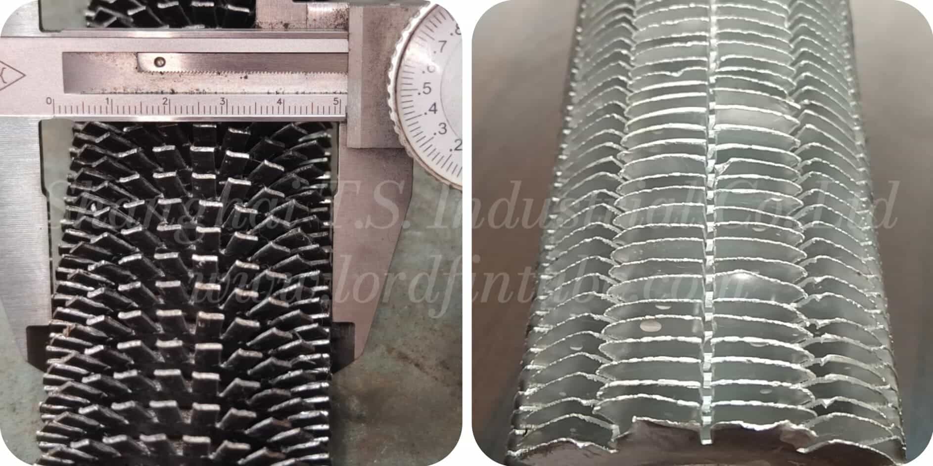
How a Serrated Spiral Fin Tube Works
A serrated spiral fin tube starts as a plain tube. A metal strip – notched along its edge – is wound helically around the tube. In the high‑frequency welded (WOS) serrated fin tubes version, the fin is continuously welded to the tube. The result: a segmented fin that looks like a series of small teeth.
Those serrations do two things:
- They force the gas to flow partly across the fin, not just along it.
- They generate tiny vortices that keep the thermal boundary layer thin.
Thinner boundary layer = lower thermal resistance = more heat transferred per square meter of fin area. Thats why you often see serrated fins in waste heat recovery and economizer service.
Types – HFW/WOS and Extruded
There are two main ways to make serrated spiral fin tubes.
High-Frequency Welded (HFW) – also called WOS (Welded On Serrated)
This is the most common type. A toothed fin strip is wrapped around the tube and welded in place with high-frequency current. The weld is metallurgical – more than 95% fusion – so theres no air gap between fin and tube. That means no contact resistance.
✔️ Weld Strength
High endurance for thermal cycling (up to 400°C).
✔️ Low Resistance
Very low thermal resistance at fin root.
✔️ Anti-fouling
Ash and scale dont cling to serrated edges.
✔️ Higher Transfer
15–20% higher heat transfer than solid fins at same pressure drop.
Extruded Serrated Finned Tubes
Extrusion forms the fin directly from the tube wall (or from a bonded bimetal sleeve). The fin and tube are one piece – no weld joint. After extrusion, the fins are machined to create the serrations.
Best for: Corrosive environments (stainless or bimetal), where absolute bond integrity is critical. Lower temperature range typically, but excellent corrosion protection.
Technical Specs (Typical)
| Parameter | Range |
|---|---|
| Base tube OD | 15 – 325 mm |
| Wall thickness | 1.65 – 16 mm |
| Tube length | up to 18,000 mm |
| Fin height | 8 – 35 mm |
| Fin thickness | 0.5 – 4.0 mm |
| Fin density | 80 – 300 fins/m (2 – 7 fpi) |
| Serration depth / width | 0.5–2.0 mm / 4–8 mm |
| Max temp. (HFW) | 400°C (higher with alloys) |
| Surface area increase | 200 – 400% vs bare tube |
| Heat transfer gain | 25 – 50% vs smooth fin |
- Carbon Steel (A179, A192, A106, SA210)
- Alloy Steel (A213, SA335)
- Stainless (304, 316, 316L, 321, 409, 410)
- ND steel, Nickel alloys
- Carbon Steel / Stainless Steel
- Aluminum / ND Steel
- Dissimilar material combinations available
Manufacturing – HFW Welding Step by Step
For HFW/WOS serrated fins:
- Clean the tube – belt sanded to remove mill scale and rust.
- Slit the fin strip – notches cut before winding.
- Wrap helically – precise pitch control.
- High-frequency weld – 200–450 kHz current heats the fin–tube interface; pressure creates a continuous weld.
- Cool and cut ends as required.
Where Are They Used?
Power generation
HRSGs, boiler economizers, superheaters, air‑cooled condensers.
Petrochemical & oil/gas
Refinery gas coolers, process heaters, air coolers, WHRUs.
Industrial processing
Chemical equipment, food drying, HVAC, wood/grain drying.
Environmental recovery
Flue gas waste heat, dry cooling towers (ash & sulfur resistance).
What the Research Says
- Journal of Thermal Science (2025): Curved serration angle of 10° improves heat transfer factor by 20% over flat serrations (Re 5,000–25,000).
- Int. J. Heat Mass Transfer (2015): Fin pitch strongly affects air‑side j and f factors; serrated welded spiral fins are the standard for economizer WHRUs.
- ASME on fluidelastic instability: For in‑line square arrays, serrated fins actually increase stability thresholds.
- DOAJ (2025): Kármán vortex shedding is key; increasing fin spacing raises shedding frequency and Nusselt number.
- ASME (1983): Serrated fins beat bare tubes in fluidized‑bed heat transfer.
Why Choose Serrated Over Solid Fins?
⚡ Better heat transfer
25–50% higher than smooth fins, lower fan power.
🧼 Self‑cleaning
Ash and scale dont build up easily.
🌿 Energy savings
20–30% lower energy consumption in many process applications.
🎛️ Design flexibility
Fin height, thickness, pitch, serration pattern tailored.
🌡️ Even fluid distribution
Fewer hot spots, uniform bundle temperature.
Ordering Checklist
- Quantity
- Material / grade
- OD x wall thickness
- Total length and finned length
- Bare end lengths / end finish
- Type: solid or serrated
- Segment width (for serrated)
- Fin height, thickness, pitch
- Fin material (if different)
Serrated spiral fin tubes arent a new invention – but they are a proven, cost-effective upgrade over solid fins in many gas‑side applications. They handle fouling better, transfer heat more efficiently, and help cut fan energy. Whether youre designing a new HRSG, revamping an economizer, or solving a chronic fouling problem, the serrated fin is worth a close look.
Lord Fin Tube supplies high‑frequency welded (WOS) serrated fin tubes, extruded serrated fin tubes, and custom configurations to ASME, ASTM, and customer specs – with full traceability. Contact us with your service conditions; well help you choose the right fin geometry.