


Shell and Tube vs Plate Heat Exchanger – A Practical Comparison
Heat exchanger selection is a critical process design decision, directly influencing project capital cost, operational energy consumption, and long-term maintenance planning for process facilities. Yet they differ substantially in thermal-hydraulic performance and mechanical limitations, with improper selection likely causing excessive capital investment or unplanned production bottlenecks.
Shell‑and‑Tube Heat Exchangers: Proven and Reliable
Introduced decades ago, the shell‑and‑tube design has matured into a stable, widely adopted solution across chemical, petrochemical, and refining industries. The construction is straightforward: a cylindrical shell houses a bundle of tubes, with tube sheets at both ends securing the tubes and providing sealing separation. Baffles are installed inside the shell to direct the shell‑side flow and enhance cross‑flow velocity. One fluid passes through the tubes (tube side), while the other flows over the tubes within the shell (shell side). Heat is continuously transferred across the tube walls.
Its core advantage lies in superior mechanical robustness and a wide operating envelope. It handles extreme pressures and elevated temperatures with ease; materials range from carbon steel to high‑grade alloys, allowing customisation for corrosive or erosive services. This makes them the preferred solution for high-demand applications in oil refining, power generation and aerospace, where operational reliability is critical. Additionally, the relatively large flow passages make them far less prone to fouling and blockage than plate designs, so they are preferred for fluids containing suspended solids, sticky residues, or high viscosity.
However, the drawbacks are equally significant. Shell‑side flow inherently creates dead zones and bypass streams, reducing overall thermal effectiveness. For a given duty, these units are bulky and require substantial plot space. Maintenance is also labour‑intensive: pulling the tube bundle for cleaning demands dedicated clearance and crane access, while mechanical or chemical cleaning of tube interiors is time‑consuming and often disruptive to continuous operation.
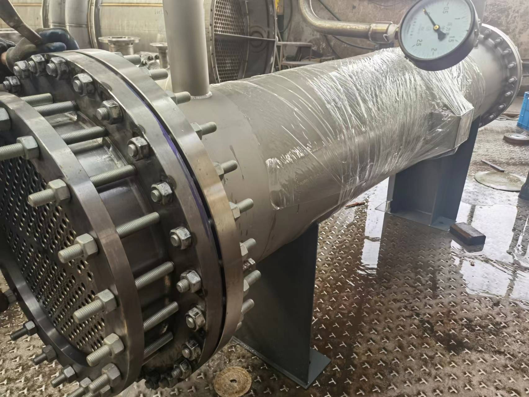
Plate Heat Exchangers: Compact and High‑Efficiency
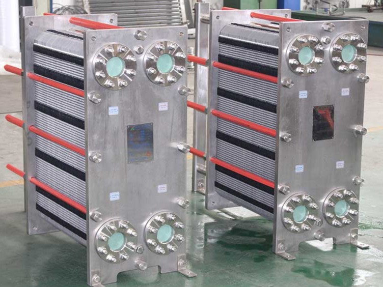
Plate heat exchangers abandon the tube‑bundle concept entirely. They consist of a stack of thin, corrugated metal plates, sealed with gaskets and compressed by a frame and tie bolts. Ports at each corner direct the hot and cold fluids into alternate channels between adjacent plates, where they flow in counter‑current direction and exchange heat through the thin plate walls.
Its most prominent advantage is outstanding heat transfer efficiency. The corrugations induce intense turbulence at very low flow velocities—Reynolds numbers as low as 50–200 are sufficient—far below the turbulent threshold for tubular designs. Overall heat transfer coefficients are typically three to five times higher than those of shell‑and‑tube exchangers. This means that for identical heat duty, the required heat transfer area is dramatically smaller.
Compactness is another hallmark. Plate thicknesses are only 0.4–0.8 mm, compared with 2.0–2.5 mm for typical tube walls. The volumetric heat transfer area can be two to five times greater than that of shell‑and‑tube units, and the total weight often falls to one‑fifth or less. Such characteristics are invaluable where floor space is constrained or where weight limits are critical (e.g., offshore platforms or skid‑mounted packages).
The design also delivers exceptional operational flexibility. Heat transfer area can be increased or reduced simply by adding or removing plates, without replacing the entire exchanger. Flow arrangement (e.g., number of passes) can be modified by rearranging the plate configuration, enabling rapid adaptation to changing process conditions.
Despite these merits, plate heat exchangers present clear operational limitations. Gasket materials and thin plates restrict operating temperatures to roughly 180 °C and pressures to about 2.5 MPa. The narrow channels are sensitive to particulates and fibrous matter, which can cause clogging. Moreover, gaskets are consumable items that degrade over time and require periodic replacement, adding to maintenance overhead.
Key Performance Indicators Compared
In practical engineering selection, several quantifiable performance metrics determine technical feasibility and economic profitability.
| Indicator | Shell‑and‑Tube | Plate | Engineering Significance |
|---|---|---|---|
| Approach temperature (terminal difference) | Typically ~5 °C | Can be as low as 1 °C | Smaller approach means higher waste‑heat recovery and lower energy consumption; plate units enable deeper heat integration. |
| Footprint (per unit duty) | Large | One‑fifth to one‑eighth of shell‑and‑tube | Compact footprint reduces civil works, piping, and structural steel costs—critical in retrofits or cramped sites. |
| Maintenance and reliability | Long maintenance‑free intervals; suited for continuous production. Cleaning is intensive and requires shutdown. | Quick disassembly for cleaning; gaskets are wear parts that raise long‑term operating costs. | Shell‑and‑tube favours processes where downtime is expensive; plate is preferred when frequent cleaning is expected and quick access is beneficial. |
| Pressure / temperature limits | High (up to several hundred bar and >500 °C with suitable materials) | Generally ≤ 2.5 MPa and ≤ 180 °C (gasketed type) | For severe service (e.g., reactor effluent, superheated steam), only shell‑and‑tube can reliably operate. |
| Fouling / particulate tolerance | Large channels, less prone to plugging | Narrow gaps, sensitive to solids and fibres | Dirty or viscous streams almost always dictate shell‑and‑tube; clean liquids with low fouling tendency are ideal for plate. |
How to Choose: A Practical Perspective
Neither exchanger type delivers universal superiority. The optimal solution depends on comprehensive evaluation of process parameters, fluid characteristics, site restrictions and full life-cycle costs.
Favour Shell‑and‑Tube When...
- Operating pressure > 2.5 MPa or temperature > 180 °C.
- Fluid is heavily fouling, contains abrasive particles, or has high viscosity.
- Plant operates continuously with minimal planned shutdowns; long intervals between maintenance are paramount.
- Corrosion or erosion risks demand exotic metallurgies that are easier to fabricate in tubular forms.
Favour Plate When...
- Fluids are clean, with low fouling tendency, and operating within moderate pressure/temperature ranges.
- Space is at a premium – e.g., offshore, skid‑mounted, or indoor installations.
- Heat recovery needs a very close approach to maximise energy savings.
- Frequent capacity changes or future expansions are anticipated; plate count can be easily adjusted.
Recent technological advances have blurred these boundaries. Welded plate designs eliminate gasket limitations, extending pressure and temperature capability. Wide‑gap plates now tolerate moderate particulate loads, broadening the application envelope. Nevertheless, for ultra‑high temperatures, extreme pressures, highly corrosive media, or severe fouling duty, the shell‑and‑tube exchanger remains unrivalled in robustness and long‑term reliability. Professional engineering evaluation should cover not only upfront capital expenditure, but also installation overhead, long-term energy consumption, maintenance cycles and equipment service life. Only through full-dimensional assessment can the most economical and reliable exchanger solution be determined for specific project scenarios.
✦ Ready to secure your next project? Talk to our technical team for tailored inspections.
© 2026 Lord Fin Tube (Shanghai T.S. Industrial Co., Ltd). All Rights Reserved.