

Lord Fin Tube--What is tube fin radiator?
Insight: Fin tube radiators can increase heat transfer efficiency by 5-10 times compared to bare tubes, making them essential components in modern thermal management systems across various industries.
This comprehensive guide explores the technical aspects, performance characteristics, and industrial applications of fin tube radiators, providing engineers and procurement specialists with essential data for informed decision-making.
What is a Fin Tube Radiator?
A fin tube radiator is an advanced heat exchanger designed to maximize heat transfer efficiency between a fluid and the surrounding environment. By incorporating extended surface areas through precisely engineered fins, these systems achieve superior thermal performance in space-constrained applications.
Performance Advantage
Fin tube radiators typically achieve heat transfer coefficients between 50-200 W/m²·K, significantly higher than standard bare tube designs (20-60 W/m²·K). This efficiency improvement translates to more compact systems and reduced operational costs.
Construction Components of Fin Tube Radiators
Material Specifications
1. Tubes: These primary conduits for fluid flow are manufactured from materials selected for optimal thermal conductivity and corrosion resistance. Tube diameters typically range from ½" to 2" with wall thicknesses between 0.028" to 0.125".
2. Headers: Engineered as distribution manifolds, headers ensure uniform flow across all tubes. Modern designs incorporate baffles and flow directors to minimize pressure drop and prevent maldistribution.
3. Fins: The critical heat transfer enhancement components. Fin density ranges from 3 to 16 fins per inch (FPI), with heights between 0.25" to 0.75". Advanced manufacturing techniques like tension winding, L-footing, and extruded fins provide optimal thermal contact.
4. Support Structures: These framework elements maintain tube alignment and fin spacing under operational stresses, including thermal expansion and vibration.
5. Fluid Connections: Strategically positioned inlet/outlet ports designed for specific flow rates and pressure requirements, with standard NPT, BSPT, or flanged connections.
Performance Comparison: Fin Tube vs. Bare Tube Radiators
| Parameter | Fin Tube Radiator | Bare Tube Radiator | Advantage |
|---|---|---|---|
| Heat Transfer Efficiency | High (5-10x improvement) | Standard | 70-85% space reduction |
| Surface Area Ratio | 15:1 to 25:1 | 1:1 | Significant area increase |
| Airside Pressure Drop | Medium to High | Low | Requires optimized fan selection |
| Material Efficiency | High | Low | Better material utilization |
| Application Flexibility | Excellent | Limited | Wider operating range |
| Maintenance Requirements | Moderate (fin cleaning) | Low | Higher in dirty environments |
How Fin Tube Radiators Work?
Heat Transfer Mechanism
Fin tube radiators operate on extended surface principles where fins act as thermal amplifiers. The temperature gradient between the hot fluid and cooler air drives conduction through tube walls, then through fins, where convection to the air occurs.
Fluid Dynamics
Optimized tube sizing and circuiting ensure turbulent flow (Re > 4000) for maximum heat transfer while maintaining acceptable pressure drops (typically 2-15 psi).
Airside Performance
Fin geometry creates boundary layer disruption, enhancing convective heat transfer coefficients. Air velocity between 2-6 m/s typically provides optimal performance with reasonable fan power requirements.
Material for Fin Tube Radiators
| Material Combination | Thermal Conductivity (W/m·K) | Corrosion Resistance | Cost Factor | Recommended Applications |
|---|---|---|---|---|
| Copper Tubes / Aluminum Fins | 200-400 (composite) | Good (with coating) | 1.2x | HVAC, Standard Industrial |
| Aluminum Tubes / Aluminum Fins | 160-220 | Fair (anodized) | 1.0x | Light Commercial, Automotive |
| Carbon Steel Tubes / Steel Fins | 45-60 | Poor (requires coating) | 0.7x | High Temperature Industrial |
| Stainless Steel Tubes / SS Fins | 15-25 | Excellent | 2.5x | Corrosive Environments, Food Processing |
Design Parameters
Key Performance Metrics
Fin Tube Radiator Industrial Applications
Power Generation: Fin tube radiators in closed-loop cooling circuits for turbines and generators achieve heat rejection rates of 5-50 MW with approach temperatures as low as 5°C.
HVAC Systems: Commercial building HVAC units utilize fin tube radiators for condenser sections, with typical capacities of 100-2000 kW and EER ratings of 10-15.
Industrial Processes: In hydraulic systems and compressor aftercoolers, fin tube radiators maintain optimal operating temperatures with heat dissipation capacities of 50-500 kW.
Tube fin radiators represent the industry standard for efficient thermal management, with continuous innovation in materials and manufacturing techniques enhancing their performance across diverse applications.
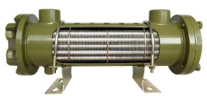
Advanced fin tube radiator design showing optimized fin spacing and tube arrangement for maximum heat transfer efficiency
Fin tube radiators
Fin tube radiators deliver superior thermal performance through extended surface technology, with typical efficiency improvements of 5-10x over bare tube designs. Material selection, fin geometry optimization, and proper airflow management are critical factors in achieving optimal performance across diverse industrial applications. Ongoing advancements in manufacturing techniques continue to expand their capabilities while reducing costs and environmental impact.