


What are Orifice Flanges?
Orifice Flanges: The Complete Guide to Flow Measurement in Industrial Piping
In the world of industrial piping systems, accurate flow measurement is essential for process control, custody transfer, and operational efficiency. Among the various flow measurement technologies available, orifice flanges remain one of the most widely used and reliable solutions. These specialized components are engineered to work in conjunction with orifice plates, creating a differential pressure measurement that enables precise flow rate determination.
What Are Orifice Flanges?
Pipe flanges of this type are specialized pipe flanges designed for the primary purpose of measuring the flow rate of liquids, gases, or steam in a pipeline. Unlike standard flanges used for general piping connections, orifice flanges serve a functional role—they are the foundation of a differential pressure flow measurement system.
The orifice flange assembly consists of a pair of flanges with an orifice plate clamped between them. The orifice plate is a thin metal disc with a precisely machined bore that creates a restriction in the flow path. As fluid passes through this restricted opening, a pressure drop occurs, and the differential pressure—measured through specially machined pressure taps in the flanges—is used to calculate the flow rate.
How Orifice Flanges Work
The operating principle of orifice flanges is based on Bernoullis principle and the conservation of energy:
- An orifice plate is installed between two orifice flanges
- Fluid flows through the precisely sized bore of the plate
- The restriction creates a pressure differential (higher pressure upstream, lower pressure downstream)
- Pressure taps machined into both flanges connect to impulse tubing
- A differential pressure (DP) transmitter calculates the flow rate
This differential pressure measurement method is both simple and highly reliable, making orifice flanges the preferred choice for countless industrial applications.
Key Design Features of Orifice Flanges
Orifice flanges are not merely standard flanges with extra holes—they are precision-engineered components with several critical design features.
1. Pressure Tap Holes
The defining characteristic of orifice flanges is the pair of pressure tapping holes machined directly into the flange body. These radial bores—typically ½" or 1" NPT threaded holes—penetrate from the outside diameter to the inside bore. One tap is positioned upstream of the orifice plate and the other downstream, allowing accurate pressure differential measurement.
The advantage of having pressure taps machined directly into the flange is that it eliminates the need for separate orifice carriers or pressure tappings in the pipe wall.
2. Jack Screws
Orifice flanges include threaded holes for jack screws—typically two per flange set. These allow operators to spread the flanges apart for orifice plate insertion, removal, or inspection without disconnecting the piping. This feature significantly simplifies maintenance and reduces downtime.
3. Special Gaskets
Orifice flange assemblies use special gaskets with tabs that extend beyond the flange outside diameter. These tabs provide quick identification and serve as handles for easy removal. Importantly, the gaskets include cutouts aligned with the tap holes to ensure pressure readings are not blocked.
4. Face Types
Orifice flanges are available with Raised Face (RF) or Ring-Type Joint (RTJ) facings, allowing compatibility with various sealing requirements and pressure classes.
Orifice Flanges vs. Standard Flanges
Understanding the differences between orifice flanges and standard flanges is essential for proper selection and application.
| Feature | Orifice Flange (ASME B16.36) | Standard Flange (ASME B16.5) |
|---|---|---|
| Standard | ASME B16.36 | ASME B16.5 |
| Pressure Taps | Two radial tap holes (½" or 1" NPT) | None |
| Jack Screws | Two jack screw holes | Not included |
| Orifice Plate | Held between the two flanges | Not applicable |
| Pressure Classes | Class 300 to 2500 | Class 150 to 2500 |
| Size Range | NPS ½" to 24" | NPS ½" to 24" |
| End Connections | Welding neck, slip-on, threaded | Multiple types |
| Primary Use | Flow measurement | General piping connection |
| Cost | 30-50% more than standard flange | Baseline |
Flange Types and Limitations per ASME B16.36
While orifice flanges share similarities with standard flanges, ASME B16.36 strictly limits their available types and pressure classes. The standard primarily covers the following:
- Welding Neck Flanges: Available in Classes 300, 400, 600, 900, 1500, and 2500.
- Slip on flanges and threaded flanges: Only available in Class 300.
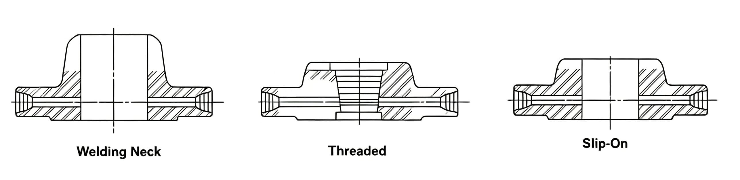
Key Limitations:
- No Class 150: Orifice flanges are not available in Class 150. This is because the pressure tap holes penetrate the flange body, reducing its structural integrity. A higher base pressure rating (starting from Class 300) is required to maintain a sufficient safety margin.
- Size Range: The standard covers flanges from NPS ½" to 24" (DN15 to DN600).
- Other Types: Other common flange types like Socket-Welding, Lap-Joint, and Blind flanges are not covered by the ASME B16.36 standard for orifice applications.
Industry Standards for Orifice Flanges
Primary Standard: ASME B16.36
The most authoritative standard governing orifice flanges is ASME B16.36 – Orifice Flanges. This standard covers:
- Pressure-temperature ratings
- Materials
- Dimensions
- Tolerances
- Testing
- Marking
The standard applies to flanges similar to those covered in ASME B16.5 but with orifice pressure differential connections. Coverage is limited to:
- Welding neck flanges: Classes 300, 400, 600, 900, 1500, and 2500
- Slip-on and threaded flanges: Class 300
International Standards (European, Japanese, British, and Others)
While ASME B16.36 is the primary standard in North America, orifice flanges are manufactured globally to meet various other specifications. Key international standards include:
European (EN)
- EN 1092-1: Primary European standard for flanges, also covers orifice flanges.
- DIN EN ISO 5167: Fluid flow measurement by pressure differential devices.
- DIN 19214: German standard for orifice flange unions.
Japanese (JIS)
- JIS B2220: Steel pipe flanges, includes orifice flanges.
- JIS Z8762: Flow measurement by orifice plates, aligns with ISO 5167.
British & Others
- BS 4504: Former British standard for circular flanges (PN designated).
- AWWA C207: Steel pipe flanges for waterworks (4–144 in.).
- NORSOK: Norwegian petroleum industry standard.
Related Standards
| Standard | Scope |
|---|---|
| ASME B16.5 | Basis for flange dimensions and materials |
| ISO 5167 | Measurement of fluid flow by pressure differential devices |
| ASME MFC-3M | Measurement of fluid flow in closed conduits |
ISO 5167 specifies the geometry and method of use of orifice plates, including installation and operating conditions. It applies to flow that remains subsonic and is not applicable to pulsating flow measurement.
Installation Requirements
Proper installation is critical for accurate flow measurement with orifice flanges.
Straight Run Pipe Requirements
To ensure accurate measurement, orifice flanges must be installed in a straight run of pipe to avoid turbulence at the orifice plate. The general requirements are:
- Minimum: 10-20 pipe diameters upstream, 5 pipe diameters downstream
- Recommended: 20-40 pipe diameters upstream, 10 pipe diameters downstream
- Ideal: 50+ pipe diameters upstream, 15 pipe diameters downstream
A commonly cited rule of thumb is 10 pipe diameters upstream and 5 pipe diameters downstream.
Additional Installation Considerations
- Orifice flanges should be installed in horizontal pipe runs whenever possible
- The pressure taps should be at the same elevation to each other
- The orifice plate must be fitted between two sections of straight cylindrical pipe of constant cross-sectional area
- Straight run requirements vary based on the type of components immediately upstream of the orifice meter
Maintenance, Removal, and Impact on Flow
A common question regarding orifice flanges is whether they need to be removed from the pipeline. The answer is no—the orifice flanges themselves are designed for permanent installation and remain in the pipeline as a fixed part of the metering station.
However, the orifice plate (the thin disc clamped between the flanges) requires regular inspection and maintenance. To facilitate this without the need for cutting or dismantling the pipework, orifice flanges are equipped with jack screws.
The maintenance procedure is straightforward:
- The line is partially depressurized to a safe working pressure.
- The jack screws are tightened to safely spread the two flanges apart.
- The orifice plate can then be easily removed for inspection, cleaning, or replacement. Gaskets are typically replaced each time the plate is removed.
Does the permanent installation affect flow velocity?
While the orifice flanges have a slightly larger mass than standard flanges, their internal bore is designed to match the pipes inside diameter. They do not protrude into the flow path. The permanent presence of the flanges themselves does not affect the flow velocity or measurement accuracy. The only flow restriction is the precisely machined bore of the orifice plate, which is intentionally there to create the differential pressure needed for flow measurement.
Regular inspection of the orifice plates edge condition is essential for maintaining long-term measurement accuracy. Depending on the service conditions, industry practice recommends inspecting the orifice plate as frequently as monthly.
Materials and Pressure Classes
Available Materials
Orifice flanges are manufactured in a wide range of materials to suit various service conditions:
| Material Type | ASTM Grade | Applications |
|---|---|---|
| Carbon Steel | A105 | Oil & gas, water, general flow measurement |
| Low-Temp Carbon | A350 LF2 | Cryogenic, LNG |
| Stainless Steel | A182 F304/304L | Chemical, pharmaceutical |
| Stainless Steel | A182 F316/316L | Chloride environments, marine, offshore |
| Alloy Steel | A182 F11 | High-temperature steam, refineries |
| Alloy Steel | A182 F22 | High-pressure, high-temperature |
| Alloy Steel | A182 F91 | Ultra-high temperature, power generation |
Pressure Classes
Orifice flanges are available in the following pressure classes:
- Class 150, 300, 400, 600, 900, 1500, and 2500
Size Range
Orifice flanges are available from NPS ½" to 24" (DN15 to DN600).
Common Applications
Orifice flanges are used across numerous industries where accurate flow measurement is essential:
Oil and Gas Industry
- Crude oil flow measurement
- Natural gas custody transfer
- Midstream gathering and transportation
Chemical Processing
- Raw material feed rates
- Product flow monitoring
Power Generation
- Feedwater flow measurement
- Steam flow measurement
Water and Wastewater
- Raw water intake measurement
- Treated water distribution
Other Applications: LNG plants, process plants.
Orifice Plate Configurations
The orifice plate itself can be configured in different ways depending on the service conditions:
| Configuration | Best Application |
|---|---|
| Concentric Bore | Standard for clean fluids |
| Eccentric Bore | Liquids with gas or solids |
| Segmental Bore | Dirty services |
| Quadrant Edge | Low flow rate applications |
Advantages of Orifice Flanges
Orifice flanges remain the most widely used flow measurement technology for several reasons:
- Simplicity – The operating principle is straightforward and well-understood
- Reliability – Proven technology with decades of successful field service
- Standardization – Governed by comprehensive ASME and ISO standards
- Ease of maintenance – Jack screws allow plate inspection without pipe disconnection
- Cost-effectiveness – Lower cost compared to many alternative flow measurement technologies
- Wide applicability – Suitable for liquids, gases, and steam across diverse industries
For more information on orifice flanges, including detailed specifications, material availability, and custom manufacturing options, please contact our technical sales team.