


Bended integral finned tube|Bent integral finned tube
Published 27 April 2024
Bended Integral Finned Tube Construction and Heat Transfer
Bended integral finned tubes represent a specialized category of heat transfer components engineered for demanding industrial environments. These components integrate extruded fins directly onto the tube surface before precision bending, creating a unified structure that maintains thermal efficiency even after complex forming operations.
The manufacturing sequence begins with seamless or welded base tubes, typically carbon or alloy steel. Fins are extruded from the tube wall material using specialized equipment, ensuring metallurgical continuity between fin and tube. Following fin formation, tubes undergo controlled bending operations to achieve required configurations—U-bends, serpentine coils, or custom geometries—while preserving fin integrity.
Why an Extruded Fin Outperforms an Attached Fin
Surface area expansion ratios typically range from 3.6 to 4.35 times the bare tube exterior, with heat transfer enhancements of 1.6–2.0x compared to plain tubes. The integral construction eliminates thermal contact resistance inherent in attached fin designs, particularly valuable in high-temperature or corrosive service conditions.
Heat entering a bended integral finned tube travels from the fin crest into the tube wall through one continuous grain structure. A wrapped or brazed fin, by contrast, forces heat across a joint that degrades as the two surfaces expand at different rates. That difference explains why an integral fin holds its duty point over thousands of thermal cycles while a mechanically attached fin slowly loses it.
| Fin Type | How the Fin Joins the Tube | Contact Resistance | Behaviour After Bending | Upper Service Temperature |
|---|---|---|---|---|
| Integral extruded | Raised from the tube wall, same material | None, continuous metal path | Fins deform but stay attached | Limited by base metal only |
| Wrap-on / tension wound | Wound under tension, sometimes tack welded | Moderate, grows with cycling | Loose fins can shift on the bend | Around 300 °C |
| Brazed or welded fin | Filler metal joint | Low but joint dependent | Joint can crack at tight radii | Filler metal dependent |
| Embedded / grooved fin | Fin foot pressed into a rolled groove | Low to moderate | Foot can work free on tight bends | Around 400 °C |
Which Materials Suit Bended Integral Finned Tube
Material selection for bended integral finned tubes depends on service conditions, thermal requirements, and environmental factors. The extrusion process for integral fins works with ductile materials capable of plastic deformation without cracking.
ASTM A179, A192, A210 for general service up to 450 °C. Offer cost-effective solutions for non-corrosive applications with excellent thermal conductivity.
Chromium-molybdenum alloys (1.25Cr-0.5Mo, 2.25Cr-1Mo) for elevated temperature service with improved oxidation resistance and creep strength.
304/304L, 316/316L for corrosive environments. Require specialized tooling and process adjustments due to work hardening characteristics.
Selected nickel alloys and duplex stainless steels for severe service conditions, subject to material-specific feasibility evaluation.
Matching Grade to Duty
| Grade | Practical Temperature Ceiling | Where It Is Usually Chosen | Extrusion Notes |
|---|---|---|---|
| ASTM A179 | 450 °C | Process water and steam coolers | Extrudes freely, high fin counts possible |
| ASTM A192 | 450 °C | High pressure steam service | Similar behaviour to A179 |
| ASTM A210 A1 / C | 450 °C | Boiler feedwater and economisers | Slightly higher tool wear |
| 1.25Cr-0.5Mo | 450–580 °C | Refinery process streams | Warm extrusion preferred |
| 2.25Cr-1Mo | 450–600 °C | Hot hydrogen and steam headers | Requires controlled tool lubrication |
| 304 / 304L | Stress limited above 550 °C | Oxidising media | Work hardens quickly, slower feed |
| 316 / 316L | Stress limited above 550 °C | Chloride bearing and acidic streams | Work hardens, tighter tool control |
Post-fin fabrication quality verification includes eddy current examination for material integrity. Supplementary testing—hydrostatic pressure tests, dimensional verification, and surface inspection—ensures compliance with project specifications. Custom material configurations undergo technical review to confirm manufacturing feasibility and performance expectations.
How Bended Integral Finned Tube Is Manufactured
The production of bended integral finned tubes follows a controlled sequence that maintains material properties while achieving precise geometrical requirements.
| Process Stage | Key Operations | Quality Controls |
|---|---|---|
| Base Tube Preparation | Material certification, dimensional verification, surface cleaning | Chemical analysis, wall thickness mapping, visual inspection |
| Fin Extrusion | Cold or warm extrusion using rotating tools, lubricant application | Fin height consistency, root thickness measurement, visual defect screening |
| Bending Operation | CNC mandrel bending, rotary draw bending, heat-assisted forming for tight radii | Radius verification, ovality checks, fin integrity assessment post-bending |
| Heat Treatment | Stress relief annealing, normalizing, or tempering based on material and application | Hardness testing, microstructural evaluation, dimensional stability verification |
| Final Processing | Straightening, cutting to length, end preparation, surface treatment | Final dimensional audit, NDE (dye penetrant, eddy current), pressure testing |
Bending considerations include minimum centerline radii based on tube OD and wall thickness. Standard practice maintains 2.5–3.0 x OD minimum bend radii for finned sections, with tighter radii achievable through process modifications. Bent regions may retain fins or feature plain sections based on application requirements and tooling constraints.
Bend Radius Against Forming Method
| Bend Radius (multiple of tube OD) | Forming Method | Effect on the Fin Crest | Typical Outcome |
|---|---|---|---|
| 3.0–4.0 | Ambient mandrel bending | Negligible distortion | Runs straight through production without special measures |
| 2.5–3.0 | Ambient mandrel bending, reduced feed rate | Slight flattening on the inner radius | Accepted on most orders after first-article approval |
| 2.0–2.5 | Mandrel support or local heating | Visible crest compression | Needs a proven sample and agreed limits |
| Below 2.0 | Specialised tooling only | Fin removal usually required | Plain tube section bent instead of finned section |
Heat treatment protocols address work hardening from fin extrusion and bending operations. Stress relief at 600–650 °C for carbon steels restores ductility without significant microstructure alteration. Critical applications may require full normalizing or tempering cycles to achieve specified mechanical properties.
Where Bended Integral Finned Tube Fits in Industrial Plants
Bended integral finned tubes serve diverse industrial sectors where efficient heat transfer in constrained spaces or complex layouts provides operational advantages.
Crude preheat trains, product coolers, and reflux condensers utilize bent finned tubes to accommodate shell-and-tube exchanger layouts with multiple tube passes. The enhanced surface area reduces exchanger footprint while maintaining thermal duty.
Ethylene cracking furnace convection sections, aromatics plant heat recovery systems, and polymerization reactor cooling employ bent configurations to maximize tube count within fired heater boxes and compact heat recovery units.
Combined cycle plant heat recovery steam generators (HRSGs), feedwater heaters, and turbine oil coolers benefit from bended integral finned tubes ability to create efficient multi-pass arrangements in limited spaces.
Turbofan and centrifugal chiller evaporators and condensers utilize tight-radius bends to create compact coil arrangements with enhanced heat transfer for refrigerant phase change processes.
Other Places These Tubes Turn Up
Beyond these primary applications, bended integral finned tubes find use in:
- Compressed air aftercoolers and intercoolers
- Lube oil cooling systems for large rotating equipment
- Process gas heaters and coolers in chemical plants
- Waste heat recovery units across manufacturing sectors
- Geothermal and solar thermal power components
Bended Integral Finned Tube Technical Specifications
Standard dimensional parameters for integral finned tubes provide baseline specifications for procurement and design activities. Custom configurations outside these ranges require technical consultation regarding manufacturing feasibility.
| Material Size Diameter/Thickness (avg) |
Number of Fins (Fins per 25.4mm) |
Fin Outside Diameter | Root Diameter | Bottom of Fin Minimum Thickness |
Outer Surface Area Average (m²/m) |
Ratio of Surface Area Outer/Inner |
Product Number |
|---|---|---|---|---|---|---|---|
| 15.88/1.91 | 19 | ≤15.98 | 12.70 | 1.27 | 12.34×10⁻² | 3.99 | |
| 15.88/2.11 | 1.47 | 4.18 | |||||
| 19.05/1.65 | ≤19.15 | 15.88 | 1.12 | 15.12×10⁻² | 3.60 | ||
| 19.05/1.91 | 1.27 | 3.69 | |||||
| 19.05/2.11 | 1.47 | 3.84 | |||||
| 19.05/2.28 | 1.65 | 3.94 | |||||
| 19.05/2.54 | 1.88 | 4.13 | |||||
| 19.05/2.77 | 2.13 | 4.35 | |||||
| 25.40/2.54 | ≤25.55 | 22.23 | 1.88 | 20.67×10⁻² | 3.65 | ||
| 25.40/2.77 | 2.13 | 3.83 | |||||
| 25.40/3.05 | 2.46 | 3.98 |
Tolerances That Decide Whether a Coil Fits
General Manufacturing Tolerances:
- Fin length tolerance: +10mm/-0mm or ±5mm as specified
- Minimum middle land length: 25±5mm
- Minimum end land length: 25±5mm
- Maximum imperfect fin length at tube ends: ≤120mm cumulative
- Maximum finned length: 19.5 meters (longer lengths subject to technical review)
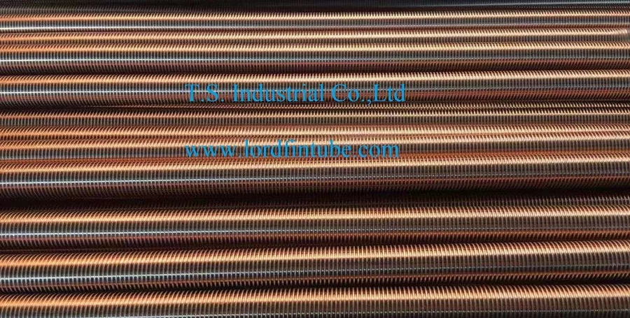
Bended integral finned tube configurations maintain fin integrity through bending operations, with bent regions available as finned or plain sections based on application requirements. Post-bending heat treatment ensures dimensional stability and mechanical property retention. Where a project also calls for a denser fin pattern on the straight runs, Integral Finned Tube variants can be produced on the same extrusion line and bent with the same tooling family.
What Affects Performance Once the Tube Is Bent
Successful implementation of bended integral finned tubes requires attention to several engineering factors. Fluid characteristics—including fouling propensity, particulate content, and corrosivity—influence fin geometry selection. Thermal-hydraulic calculations should account for bent section flow resistance and potential heat transfer coefficient variations. Mechanical design must consider differential thermal expansion between finned and plain sections, particularly in high-temperature cycling service. Installation practices should preserve fin integrity during handling and tube bundle assembly operations.
Bended Integral Finned Tube Selection Criteria
Procurement specifications for bended integral finned tubes should address both performance requirements and manufacturing constraints to ensure satisfactory project outcomes.
| Parameter | Standard Range | Critical Considerations |
|---|---|---|
| Bend Radius | 2.5–4.0 × Tube OD | Tighter radii increase material thinning; may require specialized tooling or heating |
| Fin Height | 0.8–1.6mm | Height-to-thickness ratio affects fin efficiency and mechanical stability |
| Fin Density | 16–28 fins per 25.4mm | Higher densities reduce fouling clearance; optimize for specific service conditions |
| Surface Finish | As-extruded to 3.2μm Ra | Finish affects fouling characteristics and cleanability |
| Bend Location | Minimum 100mm from tube ends | Proximity to tube sheets affects expansion allowance and sealing integrity |
For specialized applications involving extreme temperatures, corrosive media, or cyclic thermal stress, material testing coupons from bent sections provide verification of retained properties. Non-destructive examination techniques—including advanced eddy current arrays and phased array ultrasonics—offer comprehensive quality assessment without compromising component integrity.
Wall Thinning and Ovality Limits Worth Writing Into the Order
| Check Point | Common Acceptance Limit | Why It Is Measured |
|---|---|---|
| Wall thinning on the outer radius | ≤12% of nominal wall | Thinning reduces pressure containment margin at the bend |
| Ovality at the bend | ≤8% of nominal OD | Affects mandrel clearance and tube-to-tubesheet fit |
| Fin crest flattening | Agreed per drawing, often ≤15% of fin height | Protects the surface area calculation used for the thermal rating |
| Bend angle deviation | ±0.5° typical | Small errors multiply across a multi-row coil |
| Straightness of land sections | 1mm per 1000mm | Keeps the tube sliding freely through support plates |
Bended Integral Finned Tube FAQ
What separates a bended integral finned tube from a wrap-on finned tube?
On a bended integral finned tube the fins are raised out of the tube wall itself, so fin and tube share one continuous metal structure. There is no brazed, welded or tension-wound interface, which removes the contact resistance that grows in wrap-on fins after repeated thermal cycling. The trade-off is that only ductile base materials can be extruded, and very thin walls limit how deep the fins can be cut.
How tight can a bended integral finned tube be bent?
Most suppliers treat 2.5 to 3.0 times the tube outside diameter as the practical minimum centreline radius in ambient conditions. Radii between 2.0 and 2.5 times OD generally need mandrel support, slower feed rates or local heating, and each new combination of diameter, wall thickness and fin density should be proven with a first-article bend before volume production starts.
Do the fins survive the bending operation without damage?
Yes, provided the tooling is matched to the fin geometry. Fins on the outside of the bend stretch slightly while those on the inside compress, so a small amount of crest flattening is normal and accepted within agreed limits. Where a bend is very tight, the fins can be removed from the bend zone and the plain tube section bent instead.
Which heat treatment is normally applied after bending?
Carbon steel grades are usually stress relieved in the 600 to 650 °C range to restore ductility lost during extrusion and cold bending. Alloy steels may need normalising or tempering to meet specified mechanical properties. Hardness readings and, on critical orders, microstructural examination confirm that the treatment did what it was supposed to do.
What has to be stated on a purchase enquiry for bended integral finned tube?
Base tube specification and wall thickness, fin height and fin count per 25.4 mm, fin outside diameter, bend radius and the exact position of each bend, straight land length at both ends, whether the bend zone carries fins or remains plain, heat treatment condition, and the inspection regime including any pressure or non-destructive testing.