

Lord Fin Tube-Heat dissipation area of the finned tube
Heat Dissipation Area of the Finned Tube
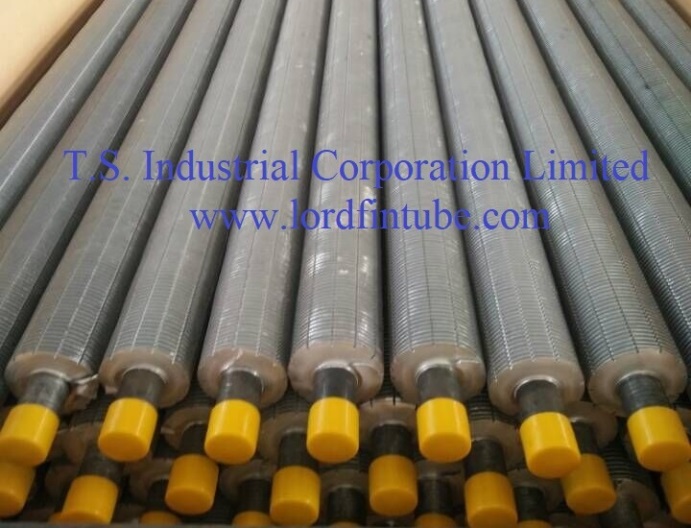
The heat dissipation area of a finned tube refers to the total surface area available for heat transfer between the fluid flowing inside the tube and the surrounding environment. Finned tubes are extended surfaces attached to the outer surface of the tube to significantly increase the heat transfer area and improve overall heat dissipation efficiency by up to 5-10 times compared to smooth tubes.
Technical Insight: The enhanced surface area of finned tubes creates turbulent flow patterns that disrupt thermal boundary layers, resulting in improved heat transfer coefficients and more efficient thermal energy exchange.
Heat Dissipation Area of the Finned Tube Calculation Formula
The total heat dissipation area can be calculated using the following fundamental formula:
Where:
- Atotal represents the total heat dissipation area (m²)
- Atube is the surface area of the smooth base tube: π × D × L (where D is outer diameter, L is tube length)
- Afins is the surface area contributed by the fins, calculated based on fin geometry and configuration
Fin Surface Area Calculations
Helical Fins
Afins = 2 × π × (Rf² - Rt²) × (L / P) × Nf
Where Rf is fin radius, Rt is tube radius, P is fin pitch, and Nf is number of fins.
Longitudinal Fins
Afins = 2 × H × L × Nf + t × L × Nf
Where H is fin height, t is fin thickness, and Nf is number of fins.
Serrated Fins
Afins = [2 × π × (Rf² - Rt²) + 2 × π × Rf × ts] × (L / P) × Nf
Where ts is serration depth, adding extra surface area.
Performance Comparison: Finned Tube Types
| Fin Type | Surface Area Increase | Heat Transfer Coefficient | Pressure Drop | Typical Applications |
|---|---|---|---|---|
| Helical Wound | 5-8x base tube | High (45-65 W/m²K) | Medium | Heat exchangers, boilers |
| Longitudinal | 3-5x base tube | Medium (35-50 W/m²K) | Low | Air coolers, radiators |
| Serrated/Notched | 7-12x base tube | Very High (60-85 W/m²K) | High | High-performance heat recovery |
| Studded | 4-6x base tube | Medium-High (40-60 W/m²K) | Medium | Furnaces, high-temp applications |
Heat Dissipation Area of the Finned Tube Practical Calculation Example
Sample Calculation: Helical Finned Tube
Given Parameters:
- Base tube diameter: 25.4 mm (1 inch)
- Tube length: 3 meters
- Fin height: 12.7 mm (0.5 inch)
- Fin thickness: 0.8 mm
- Fin pitch: 2.5 mm (400 fins per meter)
- Total fins: 1200
Calculations:
- Atube = π × 0.0254 × 3 = 0.239 m²
- Afins = 2 × π × (0.0254² - 0.0127²) × (3/0.0025) × 1200 = 4.82 m²
- Atotal = 0.239 + 4.82 = 5.059 m²
Result: The finned tube provides approximately 21 times more surface area compared to the smooth base tube alone.
Factors for Maximum Heat Dissipation
Fin Tube Material Selection
Thermal conductivity ranges: Carbon steel (45-55 W/mK), Stainless steel (15-25 W/mK), Copper (400 W/mK), Aluminum (205 W/mK). Material choice impacts both heat transfer and corrosion resistance.
Fin Efficiency
Fin efficiency (ηf) typically ranges from 60-95%. Higher fin height reduces efficiency due to temperature gradient. Optimal fin height balances added surface area with thermal performance.
Fluid Dynamics
Air/fluid velocity, viscosity, and thermal properties significantly impact convective heat transfer coefficients. Turbulent flow generally enhances heat transfer by 30-50% over laminar flow.
Heat Dissipation Area of the Finned Tube Technical
| Parameter | Low Range | Medium Range | High Range | Impact on Performance |
|---|---|---|---|---|
| Fin Density (fins/m) | 100-200 | 200-400 | 400-800 | Higher density increases area but may cause fouling |
| Fin Height (mm) | 6-12 | 12-25 | 25-50 | Higher fins increase area but reduce fin efficiency |
| Fin Thickness (mm) | 0.4-0.8 | 0.8-1.2 | 1.2-2.0 | Thicker fins improve durability but add weight/cost |
| Heat Transfer Coefficient (W/m²K) | 20-40 | 40-70 | 70-120 | Depends on fluid properties and flow conditions |
Finned Tube Industry Applications and Performance
Industry Insight: Proper calculation of heat dissipation area is critical across multiple industries including power generation (boilers, condensers), HVAC systems (air handlers, chillers), chemical processing (reactors, heat exchangers), and automotive (radiators, charge air coolers).
Field data shows that optimized finned tube designs can achieve:
- 30-50% reduction in heat exchanger size for the same thermal duty
- 15-25% improvement in overall system efficiency
- 20-35% reduction in pumping power requirements
- Extended equipment lifespan through reduced thermal stress
Need Professional Finned Tube Solutions?
Our engineering team specializes in custom finned tube designs optimized for your specific heat transfer requirements. Get expert consultation for maximum heat dissipation efficiency.
Explore Our Finned Tube ProductsHeat Dissipation Area of the Finned Tube
Understanding and accurately calculating the heat dissipation area of finned tubes is fundamental to designing efficient thermal systems. The total area depends on both the base tube geometry and the fin configuration, with proper optimization considering material properties, fluid dynamics, and operational requirements. Advanced fin designs continue to push the boundaries of heat transfer efficiency, making finned tubes indispensable in modern thermal management applications across diverse industries.