


What is low finned cooler tube?
Low Finned Cooler Tube
Low Finned Cooler Tube — what exactly does that mean, and why does it matter for industrial heat exchange? At its core, a low finned cooler tube is a plain tube that has been mechanically rolled or extruded to create a series of low-profile helical fins on its external surface. These fins typically stand between 0.90 mm and 2.50 mm tall, which is noticeably lower than the fins found on conventional high-fin tubes. The purpose is straightforward: to boost the external surface area without dramatically increasing the tubes overall diameter. This design delivers a surface area expansion of roughly 2.5 to 3 times that of a bare tube, which directly translates into higher heat transfer rates per unit of length. But why choose a low profile over a taller fin? The answer lies in the balance between thermal performance and practical operability — lower fins are less prone to fouling, easier to clean, and they maintain structural integrity under thermal cycling and vibration. For engineers and procurement specialists, understanding this trade-off is the first step toward selecting the right tube for a given duty.
Low Finned Cooler Tube Technology
Low finned cooler tubes are sophisticated heat exchanger components engineered with external fins that typically range from 0.90mm to 2.50mm in height. This strategic fin design significantly increases the external surface area of the tube — often by 2.5 to 3 times compared to plain tubes — while maintaining a compact profile that facilitates efficient heat transfer in space-constrained applications.
Unlike conventional high-fin tubes, the low-profile fin design minimizes fouling tendencies while providing substantial heat transfer enhancement. This makes low finned tubes particularly valuable in applications where maintenance accessibility is limited or where fluid streams contain particulate matter that could accumulate on more pronounced fin structures.
Enhanced Heat Transfer
The extended surface area created by the fins dramatically improves heat exchange efficiency, allowing for more compact heat exchanger designs without sacrificing performance.
Space Optimization
Low finned tubes deliver superior heat transfer per unit volume, making them ideal for applications where physical space is at a premium.
Reduced Fouling
The lower fin profile minimizes debris accumulation and simplifies cleaning procedures, reducing maintenance requirements and downtime.
How does the finning process actually work? Most low finned tubes are produced through a cold-rolling process where a plain tube is passed between finning rolls that displace material outward to form the helical fins. This work-hardens the fin tips while leaving the tubes internal bore smooth and uninterrupted. The process preserves the tubes integrity and ensures consistent fin geometry across long production runs. Which materials are suitable for this process? Copper, brass, copper-nickel alloys, and certain aluminum alloys all respond well to cold rolling, provided their ductility is sufficient. This manufacturing approach keeps costs competitive while delivering reliable, repeatable fin profiles.
Low Finned Cooler Tube Material Standards
Low finned cooler tubes are manufactured according to rigorous international standards to ensure performance consistency and material reliability across diverse operating environments.
| Standard | Scope | Common Material Grades |
|---|---|---|
| ASTM B111 / ASME SB111 | Seamless copper and copper alloy heat exchanger tubes | C12000, C12200, C44300, C68700, C70600, C71500 |
| EN12451 / EN12449 | European standards for copper alloy heat exchanger tubes | Cu-DLP, Cu-DHP, CuZn28Sn1As, CuZn20Al2As, CuNi10Fe1Mn, CuNi30Mn1Fe |
| BS British Standard | British standards for heat exchanger tubes | CZ106, CZ111, CZ110, CN102, CN106 |
| JIS H3300 | Japanese standards for copper alloy tubes | C1201, C1220, C4430, C6870, C7060, C7150 |
Which standard should you reference when specifying low finned cooler tubes? The choice often depends on the projects geographical location, customer preference, or end-user requirements. ASTM B111 remains the most widely recognized standard globally, particularly for oil and gas, power generation, and chemical processing. For European projects, EN12451 or EN12449 are commonly specified, while JIS H3300 dominates in Asian markets. Regardless of the standard, the key is to verify that the material grade, dimensional tolerances, and testing protocols align with the operational demands of your specific heat exchanger.
Low Finned Cooler Tube Chemical Composition
The performance characteristics of low finned cooler tubes are directly influenced by their precise chemical composition, which is carefully controlled during manufacturing to ensure optimal thermal conductivity, corrosion resistance, and mechanical strength.
| Material Type | Chemical Composition | Key Properties |
|---|---|---|
| Copper (C12000/C12200) | Cu ≥ 99.90 | Excellent thermal conductivity, good corrosion resistance |
| Copper-Zinc-Tin (Admiralty) | 70.0 ≤ Cu ≤ 73.0; 0.8 ≤ Sn ≤ 1.2; Zn Rem; 0.02 ≤ As ≤ 0.06 | Superior corrosion resistance in freshwater and marine environments |
| Aluminum Brass | 76.0 ≤ Cu ≤ 79.0; 1.8 ≤ Al ≤ 2.5; Zn Rem; 0.02 ≤ As ≤ 0.06 | Enhanced resistance to impingement attack and dezincification |
| Copper-Nickel Alloys | 9.0 ≤ Ni ≤ 33.0; 0.4 ≤ Fe ≤ 1.8; Cu Rem | Excellent marine corrosion resistance, biofouling resistance |
Why does chemical composition matter so much for low finned cooler tubes? The alloying elements directly affect how the tube behaves under heat, pressure, and corrosive attack. For instance, the addition of arsenic in Admiralty brass inhibits dezincification — a form of selective corrosion that can weaken the tube wall over time. Copper-nickel alloys, on the other hand, offer exceptional resistance to seawater corrosion and biofouling, making them the go-to choice for marine heat exchangers. When selecting a material, consider not just the tube-side fluid but also the shell-side environment, as both sides contribute to the overall corrosion risk.
Low Finned Cooler Tube Dimensions
Low finned cooler tubes are available in precise dimensional ranges to accommodate various heat exchanger designs and performance requirements.
Standard Dimensions
Outside Diameter: 12mm - 30mm
End Wall Thickness: 1.2mm - 3.25mm
Fin Height: 0.90mm - 2.50mm
Wall Under Fin: 0.65mm - 2.82mm
Performance Considerations
The fin density typically ranges from 630 to 1575 fins per meter (16-40 fins per inch), creating an optimal balance between increased surface area and minimal flow resistance.
The finned section generally covers 80-90% of the tube length, with plain ends provided for proper seating in tube sheets.
| Tube OD (mm) | End Wall Thickness (mm) | Wall Under Fin (mm) | Fin Height (mm) | Fins per Meter |
|---|---|---|---|---|
| 12.7 | 1.25 | 0.65 | 0.90 | 1020 |
| 15.9 | 1.65 | 0.95 | 1.20 | 945 |
| 19.1 | 1.85 | 1.10 | 1.50 | 870 |
| 25.4 | 2.40 | 1.60 | 2.00 | 740 |
| 31.8 | 3.00 | 2.10 | 2.50 | 630 |
How do you decide which fin height and density to specify? The decision hinges on the thermal duty and the allowable pressure drop. Higher fins and denser spacing increase the surface area, which boosts heat transfer, but they also constrict the shell-side flow, raising pressure drop. For clean gas or low-viscosity liquids, you can afford denser finning. For dirty or viscous fluids, a lower fin height with wider spacing is often the wiser choice, as it reduces fouling and cleaning frequency. The table above gives typical combinations — always consult with your fin tube supplier to confirm availability for your specific OD and wall thickness.
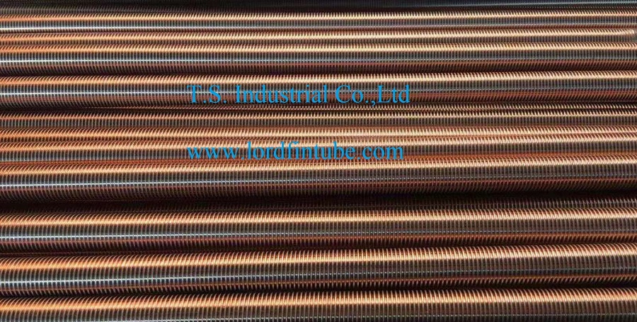
Microscopic view of low finned cooler tube showing precise fin geometry and surface structure
Low Finned Cooler Tube Applications
Low finned cooler tubes serve critical functions across multiple industries where efficient heat transfer is essential for process optimization, energy efficiency, and equipment protection.
HVAC, refrigeration, and process heat exchangers benefit from compact designs with enhanced thermal performance.
Cooling process fluids, condensing vapors, and maintaining optimal temperatures in refining operations.
Critical components in condensers and heat exchange systems for steam condensation and gas cooling.
Temperature control in reactors, distillation columns, and various chemical manufacturing processes.
Pasteurization, sterilization, and cooling processes requiring hygienic heat transfer surfaces.
Efficient cooling of compressed air to improve system efficiency and prevent moisture issues.
Evaporators and condensers in commercial and industrial refrigeration applications.
Solar thermal systems and geothermal heat pumps for efficient renewable energy utilization.
Which industries are adopting low finned cooler tubes most rapidly? The renewable energy sector is seeing strong growth, particularly in solar thermal plants and geothermal installations where compact, efficient heat exchangers are essential. Additionally, the push for higher efficiency in data center cooling has led to increased use of low finned tubes in closed-loop cooling systems. In the oil and gas industry, low finned tubes remain a staple for offshore platforms where space is at a premium and maintenance access is challenging. The common thread across all these applications is the need for reliable, long-term thermal performance in a compact footprint.
Low Finned Cooler Tube Benefits
Low Finned Cooler Tube Selection
When specifying low finned cooler tubes for a particular application, several critical factors must be considered to ensure optimal performance and longevity:
Operating Environment
The chemical composition of both the tube-side and shell-side fluids will determine the appropriate material selection. Corrosive environments may require copper-nickel alloys or specially treated surfaces, while clean applications may utilize standard copper or brass compositions.
Thermal Performance Requirements
The required heat transfer rate, temperature differentials, and flow rates will influence the optimal fin height, density, and tube diameter. Higher fin densities provide greater surface area but may increase pressure drop and fouling potential.
Mechanical Constraints
Operating pressures, vibration potential, and thermal expansion characteristics must be considered to ensure structural integrity throughout the equipments service life.
Maintenance Considerations
Applications with high fouling potential may benefit from lower fin heights and wider fin spacing to facilitate cleaning and reduce maintenance frequency.
What is the most common mistake made when selecting low finned cooler tubes? Over-specifying fin density without considering the shell-side fouling tendency. Dense finning looks attractive on paper because it maximizes surface area, but in practice, it can lead to rapid performance degradation if the shell-side fluid carries particulates or tends to form deposits. A better approach is to calculate the required surface area based on the clean heat transfer coefficient, then apply a fouling factor that accounts for the expected deposit thickness. Often, a slightly lower fin density with a wider spacing will deliver more stable long-term performance and lower maintenance costs. Always consult with an experienced thermal designer before finalizing your fin specification.
Low Finned Cooler Tube Innovations
The development of low finned cooler tube technology continues to evolve, with recent advancements focusing on enhanced surface treatments, alternative materials including specialized alloys and composites, and precision manufacturing techniques that further optimize thermal performance while reducing material requirements. The integration of smart monitoring systems with low finned tube heat exchangers represents an emerging trend, enabling real-time performance optimization and predictive maintenance capabilities.
Which innovations are shaping the future of low finned cooler tubes? One promising area is the development of hybrid fin profiles that combine low and high fin geometries on the same tube, allowing for tailored heat transfer along the tube length. Another is the use of additive manufacturing to produce fin structures with complex internal geometries that were previously impossible to achieve with conventional rolling. Coatings are also advancing — new anti-fouling and anti-corrosion coatings are being formulated specifically for low finned surfaces, extending tube life in aggressive environments. Finally, digital twins of heat exchangers are becoming more common, allowing operators to simulate performance under various conditions and plan maintenance activities more effectively. These innovations are making low finned tubes even more versatile and cost-effective for a widening range of applications.