


Does Finned tube have the more fins the better?
How to choose fin pitch?
Does Finned tube have the more fins the better? How to choose fin pitch?
When it comes to finned tubes, it is not necessarily true that "the more fins, the better." The number of fins on a finned tube should be optimized based on the specific heat transfer requirements and operational considerations of the application. Adding more fins does increase the surface area available for heat transfer, but it also has certain implications that need to be taken into account. The fin pitch — the distance between adjacent fins — is a critical parameter that directly influences thermal performance, airflow dynamics, and long-term reliability. Rather than simply maximizing fin count, engineers must evaluate how fin pitch interacts with the entire system.
Understanding the role of fin pitch begins with recognizing that heat exchangers operate under diverse conditions. What works for a clean, indoor air-cooling unit may fail entirely in a dusty industrial environment. Similarly, the same fin pitch that delivers exceptional heat transfer at low air velocities might cause excessive pressure drop at higher flow rates. This is why selecting the right fin pitch is not a one-size-fits-all decision but a tailored engineering choice.
What to consider when choosing fin pitch?
Several interrelated factors influence the decision on fin pitch. Each application brings its own set of priorities, and the optimal choice often involves trade-offs. Below are the primary considerations that guide the selection process:
1. Heat Transfer Efficiency
Increasing the number of fins does improve the heat transfer efficiency since it increases the surface area available for heat exchange. However, there is a point of diminishing returns where adding more fins may not significantly enhance heat transfer but can increase pressure drop, leading to higher energy consumption in fluid circulation. With a tighter fin pitch, the boundary layer between the fin surface and the air becomes thinner, which can improve convective heat transfer — but only up to a certain threshold. Beyond that, the air may not fully penetrate the gap between fins, reducing the effective heat transfer area.
2. Air or Fluid Flow Resistance
More fins can result in increased resistance to the flow of air or fluid around the tube. This higher resistance can lead to increased pressure drop, requiring more powerful fans or pumps to overcome the added resistance and maintain adequate flow rates. The relationship between fin pitch and pressure drop is nonlinear: reducing the pitch by half can increase the pressure drop by a factor of three or more, depending on the fin geometry and Reynolds number. This has direct implications for operating costs and system sizing.
3. Manufacturing Complexity and Cost
As the number of fins increases, the complexity of manufacturing the finned tubes also increases. This can result in higher production costs, especially for customized or specialized designs. Tighter fin pitches require more precise tooling, tighter tolerances, and often slower production speeds. For large-scale projects, the cumulative cost difference between a 3 mm pitch and a 5 mm pitch can be substantial, influencing the overall project budget.
4. Cleaning and Maintenance
A higher number of fins can make it more challenging to clean the finned tubes, as it increases the number of surfaces that need to be accessed and cleaned. This can be a consideration in applications where frequent maintenance and cleaning are required. In environments with airborne particulates — such as steel mills, cement plants, or agricultural drying facilities — a tighter fin pitch accelerates fouling and increases the frequency of shutdowns for cleaning. Conversely, a wider pitch allows for easier mechanical cleaning and reduces the risk of bridging between fins.
How does fin pitch affect heat transfer efficiency?
The relationship between fin pitch and heat transfer efficiency is governed by the interplay of surface area, convection coefficients, and air-side thermal resistance. When the fin pitch is reduced, the surface area per unit length increases, which theoretically enhances the total heat transfer. However, the actual gain is moderated by the fact that the air-side heat transfer coefficient decreases as the gap between fins narrows, due to increased boundary layer interference. At very tight pitches, the air may not flow effectively between the fins, leading to "dead zones" where heat transfer is minimal.
From a practical standpoint, the optimal fin pitch is the one that maximizes the product of surface area and heat transfer coefficient while minimizing pressure drop. This is often expressed in terms of the Colburn j-factor and the friction factor f. For most industrial finned tubes, the optimal fin pitch falls in the range of 3 to 6 mm, depending on the air velocity and the fin geometry. At lower air velocities (1–2 m/s), a tighter pitch (3–4 mm) can be beneficial, while at higher velocities (3–5 m/s), a wider pitch (5–6 mm) may be more efficient due to reduced pressure drop.
What is often overlooked is the effect of fin pitch on the fin efficiency itself. Fin efficiency — the ratio of actual heat transfer to the theoretical maximum if the entire fin were at the base temperature — decreases as the fin height increases or the fin thickness decreases. With a tighter pitch, the fins are often shorter or thinner, which can improve fin efficiency. However, the overall heat transfer per unit length may still be lower if the air-side resistance dominates. Therefore, choosing the right fin pitch requires a holistic analysis that accounts for both fin-side and air-side thermal resistances.
Which fin pitch to choose for different applications?
Different operating environments and performance requirements call for different fin pitch values. The table below provides a general guideline for selecting fin pitch based on application type, expected air velocity, and fouling propensity. This data is derived from field experience and laboratory testing across a range of industrial heat exchangers.
| Fin Pitch Range (mm) | Typical Applications | Heat Transfer Performance | Pressure Drop | Cleaning & Maintenance |
|---|---|---|---|---|
| 2.0 – 3.5 mm | High-efficiency HVAC, refrigeration condensers, cleanroom systems | Excellent (high surface density) | High (requires powerful fans) | Challenging (frequent cleaning needed) |
| 3.5 – 5.0 mm | Air-cooled heat exchangers, process coolers, gas turbine inlet cooling | Good (balanced performance) | Moderate (acceptable for most fans) | Moderate (routine maintenance sufficient) |
| 5.0 – 8.0 mm | Dusty environments (cement, mining), boiler air preheaters, waste heat recovery | Fair (lower surface area) | Low (energy-efficient) | Easy (accessible for mechanical cleaning) |
| 8.0 – 12.0 mm | High-fouling services (flue gas, biomass), heavy industrial boilers | Low (designed for fouling tolerance) | Very low (minimal resistance) | Very easy (self-cleaning tendency) |
It is important to note that these ranges are starting points rather than fixed rules. The actual fin pitch selection should be validated through detailed thermal calculations that account for the specific fluid properties, operating temperatures, and desired heat duty. Many manufacturers offer customized fin pitches within these ranges to meet unique project specifications.
Why does choosing fin pitch matter for pressure drop?
Pressure drop is often the limiting factor in heat exchanger design, especially when the system is retrofitted into an existing duct or piping network. The choice of fin pitch directly affects the air-side pressure drop, which in turn determines the fan power consumption and the overall system efficiency. A tighter fin pitch increases the friction factor because the air experiences more shear stress as it flows through the narrow gaps between fins. This effect is amplified at higher air velocities, making the pressure drop penalty disproportionately severe.
For example, reducing the fin pitch from 5 mm to 3 mm at an air velocity of 3 m/s can increase the pressure drop by approximately 60–80%, depending on the fin geometry and tube arrangement. Over the lifetime of a heat exchanger, this additional pressure drop can translate into thousands of dollars in additional electricity costs for the fan or blower. In some cases, the increased pressure drop may even require upgrading the fan motor, adding capital expense to the project.
On the other hand, a wider fin pitch reduces the pressure drop but also lowers the heat transfer coefficient per unit length. This means that to achieve the same heat duty, the heat exchanger must be longer or larger in cross-section, which increases the footprint and material cost. The trade-off between pressure drop and heat transfer is a classic engineering optimization problem, and the right fin pitch is the one that minimizes the total cost — including capital, energy, and maintenance — over the equipments service life.
For systems with variable flow rates, such as those using variable frequency drives (VFDs), the pressure drop characteristics become even more important. At reduced flow, the pressure drop decreases quadratically, which can improve part-load efficiency. A well-chosen fin pitch that balances full-load and part-load performance can yield significant energy savings over time.
How to choose fin pitch with maintenance in mind?
Maintenance is often an afterthought in heat exchanger design, yet it accounts for a significant portion of the total cost of ownership. The fin pitch plays a crucial role in determining how easily the heat exchanger can be cleaned and how frequently cleaning is required. In applications where the air stream carries dust, soot, or other particulates, a tighter fin pitch accelerates fouling because the narrow gaps trap particles and restrict airflow. Once fouled, the heat transfer performance degrades rapidly, and the pressure drop increases, further reducing efficiency.
For such environments, selecting a wider fin pitch — typically 5 mm or more — can dramatically reduce the cleaning frequency. The wider spacing allows particles to pass through the fin bundle rather than accumulate on the fin surfaces. In some cases, a wider pitch also enables in-situ cleaning methods such as steam blowing or high-pressure water jetting, which are not feasible with very tight pitches. For heat exchangers that are difficult to access, such as those located at height or in confined spaces, the ability to clean effectively without dismantling the unit is a major advantage.
Conversely, in clean environments such as air-conditioned spaces or electronic cooling applications, fouling is minimal and a tighter fin pitch can be safely used to maximize heat transfer. In these scenarios, the maintenance interval can be extended to months or even years, making the cleaning difficulty less of a concern. The key is to match the fin pitch to the expected fouling rate and the available cleaning resources.
Another maintenance-related consideration is the corrosion resistance of the fin material. Tighter fin pitches can create crevices where moisture and corrosive agents accumulate, accelerating localized corrosion. This is particularly relevant in coastal or industrial environments with high humidity and aggressive chemicals. In such cases, a wider fin pitch reduces the crevice effect and allows for better drainage, which can extend the service life of the finned tube.
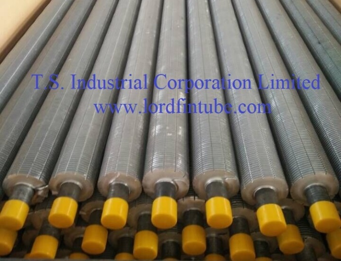
serrated Finned Tube
Therefore, the optimal number of fins on a finned tube depends on various factors, including the heat transfer requirements, fluid or air velocities, available pressure, space limitations, and cost considerations. It is essential to conduct a detailed heat transfer analysis and consider the specific requirements of the application to determine the appropriate fin density and configuration for achieving the desired heat transfer performance while balancing other factors such as pressure drop and maintenance requirements. In practice, the final decision on fin pitch is often reached through iterative calculations and, when possible, validated by prototype testing or reference to similar installations.
For procurement teams and design engineers, a systematic approach that starts with defining the operating envelope — including temperature range, flow rate, fouling tendency, and allowable pressure drop — will narrow down the feasible fin pitch range. From there, a cost-benefit analysis that weighs the incremental heat transfer gain against the added pressure drop and maintenance burden will point to the most economical and reliable choice. Ultimately, the right fin pitch is the one that delivers the required thermal duty at the lowest life-cycle cost, not merely the one with the most fins per unit length.