


Coaxial condenser is a widely used water-cooled heat exchanger in small refrigeration systems. Featuring compact structure and high heat transfer efficiency, it plays a vital role in refrigerant air conditioners, water chillers, heat pump units and other equipment. Composed of two concentric pipes of different diameters, it realizes efficient refrigerant condensation through counter-flow heat exchange and serves as an essential core component of the refrigeration cycle.
Nomenclature Note: The coaxial condenser is the formal engineering term. It is also widely known as the double tube condenser or tube-in-tube condenser in the refrigeration industry. The three names refer to the same nested double-pipe heat exchange device, which is distinguished by different naming perspectives: coaxial structure, double-tube composition, and tube-in-tube morphological characteristics.
1. Basic Structure
The coaxial condenser adopts a nested double-pipe structure, which is usually bent into a spiral or serpentine shape to adapt to narrow and limited installation spaces.
- Outer pipe: Generally made of seamless steel pipe with a diameter of about 50mm, serving as the flow channel for refrigerant with excellent pressure resistance.
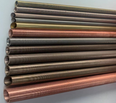
- Inner pipe: Equipped with single or multiple copper tubes (or low-finned copper tubes) for cooling water delivery. Copper material delivers outstanding thermal conductivity, and the low-fin structure can effectively strengthen heat transfer performance.
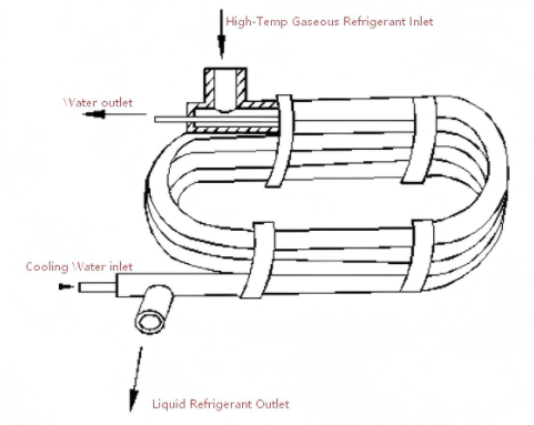
- Interfaces and brackets: Fitted with inlet and outlet ports for refrigerant and cooling water, as well as fixed brackets, facilitating on-site installation and pipeline connection.
2. Working Principle
The core working mode is counter-flow heat exchange. The two heat exchange media flow in opposite directions to maximize the heat transfer temperature difference and achieve optimal heat exchange efficiency, known as coaxial condenser working principle.
Refrigerant side
High-temperature and high-pressure gaseous refrigerant enters the annular gap between the inner and outer pipes through the upper inlet of the outer pipe, flows downward along the inner wall of the outer pipe, condenses into liquid after contacting and exchanging heat with the low-temperature wall of the inner pipe, and finally flows out from the lower outlet of the outer pipe into the liquid receiver.
Cooling water side
Cooling water flows into the inner cavity of the inner pipe from the lower inlet, flows upward from bottom to top, absorbs the heat released by the refrigerant, and is discharged from the upper outlet to take away the condensation heat.
Heat transfer core
Heat is transferred from the refrigerant side to the cooling water side through the pipe wall of the inner pipe. The counter-flow design maintains a large temperature difference between the two media throughout the heat transfer process. Its heat transfer coefficient can reach 800-1200W/(m²·K), ensuring remarkable heat exchange performance.
3. Core Characteristics
Advantages
- High heat transfer efficiency: The combination of counter-flow, high thermal conductivity copper and low-fin enhancement enables better performance than shell-and-tube condensers of same volume.
- Compact structure: Spiral or serpentine bending design realizes small size and light weight, greatly saving floor space.
- Simple manufacturing process: Pipe nesting and integral bending is mature, with low cost and high adaptability for mass production.
- Strong adaptability: Withstands high-pressure working conditions and compatible with various refrigerants like R22, R410A and CO₂.
Limitations
- High metal consumption: Unit heat transfer area consumes more copper and steel, leading to relatively higher long-term cost.
- Difficult cleaning and maintenance: Removal of scale and oil dirt requires disassembly; regular acid pickling mandatory.
- Limited heat transfer area: Excessively long coiled pipes cause liquid accumulation, reducing area utilization; applicable for units ≤25kW.
| Parameter | Coaxial Condenser | Shell-and-Tube (Small size) |
|---|---|---|
| Heat transfer coefficient (W/m²·K) | 800-1200 | 500-800 |
| Footprint | Compact (spiral) | Larger |
| Cleaning difficulty | High (disassembly required) | Moderate (detachable ends) |
| Max cooling capacity | ≤25kW (typical) | 10-100kW+ |
4. Main Application Scenarios
Household central AC, wall-mounted & floor-standing units (3-10kW)
Injection molding, laser cutting, electronics manufacturing (5-25kW)
Air-source heat pump water heaters, commercial ice makers
CO₂ transcritical heat pumps, small cold storage units
5. Maintenance and Selection Guidelines
Maintenance Guidelines
- Regular cleaning: Acid pickling once a year under poor water quality; once every 2-3 years under good quality.
- Leakage prevention inspection: Regularly check sealing interfaces and welding positions.
- Flow rate control: Keep cooling water flow velocity at 1-2m/s to avoid scaling or high energy consumption.
Selection Guidelines
- Cooling capacity matching: Prefer units with rated cooling capacity ≤25kW.
- Material adaptation: Copper inner pipes for conventional conditions; stainless steel for corrosive media.
- Installation space matching: Spiral type for compact narrow spaces, serpentine for strip-shaped positions.
6. Conclusion
With the core advantages of simple structure, high heat transfer efficiency and small occupied space, coaxial condensers have become mainstream condensing equipment for small refrigeration systems. Despite the shortcomings of inconvenient daily maintenance and limited single-unit heat transfer area, it has irreplaceable cost performance and practicality in refrigeration scenarios with a cooling capacity below 25kW. With the upgrading of material technologies such as stainless steel inner pipes and enhanced heat transfer coatings, coaxial condensers will further expand their application boundaries in heat pump systems, new energy refrigeration and other emerging fields.