

Cold Bending Boiler Tube vs Hot Bending Boiler Tube
Cold Bending vs Hot Bending
An in-depth analysis of tube bending methodologies for engineers, fabricators, and procurement specialists in high-pressure systems
In industrial applications where pressure integrity and material performance are non-negotiable, the choice between cold bending tube bend and hot bending tube bend processes can determine the success or failure of your entire system. While both methods achieve the same geometric outcome—a curved tube—their impact on material properties, dimensional accuracy, and long-term performance varies significantly.
Cold Bending Boiler Tube and Hot Bending Boiler Tube
Cold Bending Tube Bend Process
Cold bending represents a sophisticated metal forming technique that plastically deforms tubes at ambient temperatures without external heat application. This process relies on precisely calculated mechanical forces to reshape the material while maintaining its original metallurgical properties.
Cold Bending Process Flow:
- Material Assessment - Verify tube specifications, including wall thickness, diameter, and material certification
- Surface Preparation - Thorough cleaning to eliminate contaminants, oils, and oxide layers that could compromise bend quality
- Internal Support Strategy - Implementation of mandrels, filler media, or internal pressure systems to prevent cross-sectional deformation
- Precision Bending - Application of controlled force through CNC mandrel bending equipment with real-time monitoring
- Springback Compensation - Accounting for material memory by over-bending to achieve target angles
- Post-Processing - Removal of support systems and surface refinement
Hot Bending Tube Bend Process
Hot bending involves elevating the tube material to specific temperature thresholds—typically between 850°C to 1100°C depending on alloy composition—to reduce yield strength and facilitate plastic deformation with significantly less force.
Hot Bending Process Flow:
- Thermal Planning - Determination of appropriate heating parameters based on material composition and wall thickness
- Filler Media Application - Introduction of specialized sands or low-melting-point alloys to maintain cross-sectional integrity during heating and bending
- Controlled Heating - Precise application of heat to the bending zone using induction, resistance, or furnace heating methods
- Thermal Bending - Formation of the bend while maintaining critical temperature ranges
- Stress Relief Protocol - Implementation of controlled cooling cycles, potentially including quenching and tempering sequences
- Surface Restoration - Removal of scale through shot blasting, pickling, or mechanical descaling processes
Technical Comparison: Cold Bending vs Hot Bending
| Technical Parameter | Cold Bending Tube Bend | Hot Bending Tube Bend |
|---|---|---|
| Wall Thickness Range | 0.5mm to 12mm (optimal for thin-wall applications) | 12mm to 100mm+ (essential for thick-wall components) |
| Minimum Bend Radius | 1.5D (where D is tube diameter) for most materials | 3D minimum, with 5D recommended for critical applications |
| Material Considerations | Excellent for stainless steels, aluminum, copper, and high-alloy materials with good ductility | Preferred for carbon steels, low-alloy steels, and materials with limited cold-formability |
| Metallurgical Impact | Introduces work hardening; may require subsequent annealing for certain applications | Alters grain structure; necessitates controlled heat treatment to restore mechanical properties |
| Dimensional Accuracy | ±0.5° angular tolerance; ±0.1mm on radius for precision applications | ±2° angular tolerance; typically requires secondary calibration for precise installations |
| Surface Integrity | Maintains original surface finish; minimal oxidation or discoloration | Requires post-bending surface treatment to remove scale and restore corrosion resistance |
| Production Efficiency | Rapid cycle times; suitable for high-volume production with minimal setup | Extended processing times due to heating and cooling cycles; typically batch-oriented |
| Tooling and Equipment | CNC mandrel benders with interchangeable tooling for various diameters | Heating systems, bending fixtures, and heat treatment facilities required |
| Cost Considerations | Lower energy consumption; reduced secondary processing requirements | Higher energy inputs; additional costs for heat treatment and surface restoration |
Application-Specific Recommendations
Cold Bending Applications
Cold bending tube bend technology excels in scenarios requiring precision, material integrity preservation, and high-volume production efficiency.
- Heat Exchanger Tubing - Maintaining precise U-bend geometries in condenser and heat exchanger applications
- Instrumentation Lines - Small diameter tubing for control systems where dimensional accuracy is critical
- Architectural Applications - Handrails, structural elements where surface finish matters
- Automotive Exhaust Systems - Complex mandrel bends in stainless steel requiring consistent wall thickness
- Aerospace Hydraulic Lines - High-precision bending of thin-wall tubing for flight-critical systems
Hot Bending Applications
Hot bending tube bend processes are indispensable for challenging materials, extreme thicknesses, and applications where cold forming would compromise material integrity.
- Power Generation Piping - Main steam lines and high-temperature feedwater systems in boilers
- Petrochemical Transfer Lines
- Heavy Wall Pressure Vessel Nozzles - Transition pieces between vessels and connecting piping
- Marine Engine Exhaust Systems - Large diameter bends in thick materials for ship applications
- Nuclear Power Components - Primary coolant loop piping where material certification is rigorous
Advanced Technical Considerations for Tube Bending Selection
Material Management
Cold bending requires precise compensation for material springback, which varies by alloy, temper, and wall thickness. Experienced fabricators develop proprietary algorithms to predict and accommodate this phenomenon.
Weld Procedure Qualifications
Hot bent components often require post-bend heat treatment, which may necessitate re-qualification of welding procedures if additional fabrication is needed after bending.
Non-Destructive Testing Compatibility
The surface conditions resulting from each process affect NDT reliability. Cold bending typically produces surfaces more compatible with ultrasonic and dye penetrant inspection.
Life Cycle Cost Analysis
While cold bending often has lower initial costs, hot bending may provide better long-term performance in high-temperature cyclic service where residual stresses from cold working could lead to premature failure.
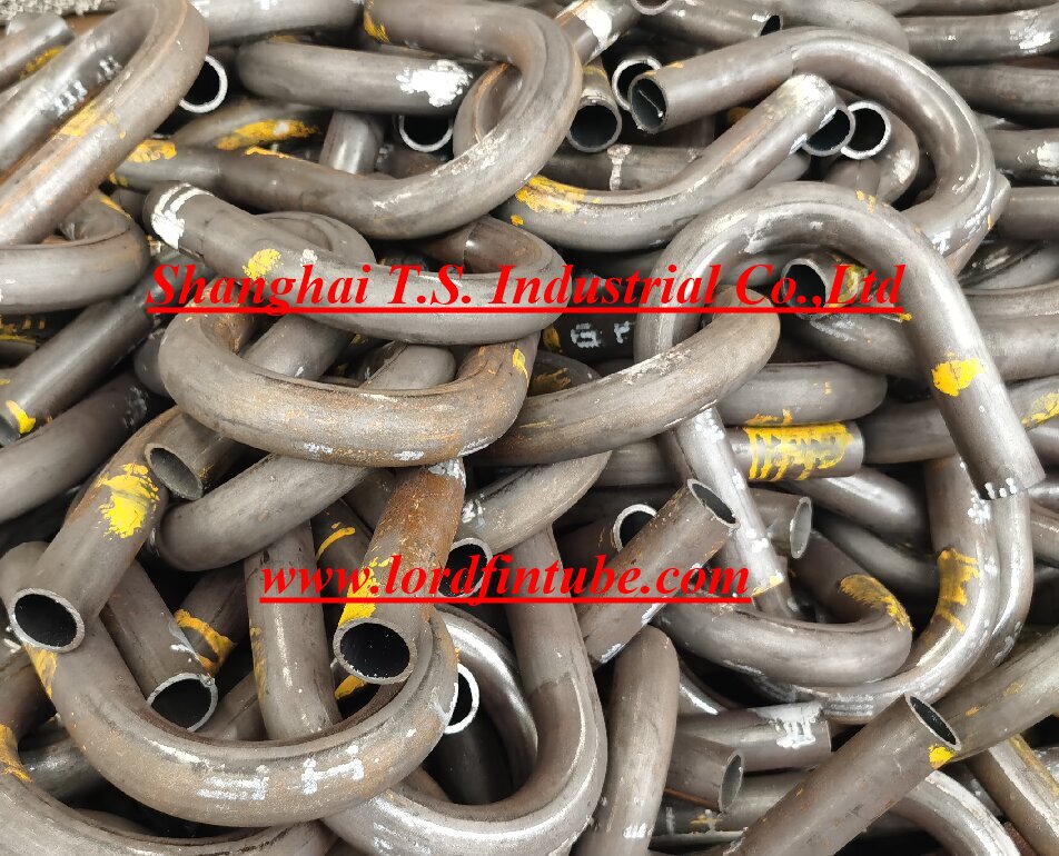
Visual comparison of cold bending (left) and hot bending (right) tube applications in industrial settings
Decision Framework: Selecting the Right Bending Method
Choosing between cold bending tube bend and hot bending tube bend technologies requires a systematic evaluation of multiple factors. For thin-wall applications (below 12mm) where precision, surface finish, and production efficiency are priorities, cold bending typically delivers superior results. When working with thick-walled components (above 12mm), high-strength alloys with limited ductility, or applications requiring minimal residual stress, hot bending becomes the necessary choice.
Modern fabrication facilities often maintain capabilities in both technologies, allowing engineers to select the optimal process based on specific project requirements rather than equipment limitations. The most successful projects result from early collaboration between design engineers and fabrication specialists to optimize designs for manufacturability while meeting performance specifications.