ASTM A1012 Condenser and Heat Exchanger Tubes With Integral Fins
ASTM A1012 Standard Specification for Seamless and Welded Ferritic, Austenitic and Duplex Alloy Steel Condenser and Heat Exchanger Tubes With Integral Fins
1. ASTM A1012 Scope
1.1 This specification describes seamless and welded Ferritic, austenitic and duplex alloy steel tubing on which the external or internal surface, or both, has been modified by a cold forming process to produce an integral enhanced surface for improved heat transfer. The tubes are used in surface condensers, evaporators, heat exchangers and similar heat transfer apparatus in unfinned end diameters up to and includ- ing 1 in. (25.4 mm). Boiler tubes are excluded.
1.2 The values stated in inch-pound units are to be regarded as the standard. The values given in parentheses are for information only.
1.3 The following precautionary statement pertains to the test method portion only: Section 12 of this specification: This standard does not purport to address all of the safety concerns, if any, associated with its use. It is the responsibility of the user of this standard to establish appropriate safety and health practices and determine the applicability of regulatory limita- tions prior to use.
2. ASTM A1012 Referenced Documents
2.1 ASTM Standards:
A 213/A 213M Specification for Seamless Ferritic and Austenitic Alloy-Steel Boiler, Superheater, and Heat- Exchanger Tubes2
A 249/A 249M Specification for Welded Austenitic Steel Boiler, Superheater, Heat-Exchanger and Condenser Tubes2
A 268/A 268M Specification for Seamless and Welded Ferritic and Martensitic Stainless Steel Tubing for General Service2
A 269/A 269M Specification for Seamless and Welded Austenitic Stainless Steel Tubing for General Service2
A 450/A 450M Specification for General Requirements for Carbon, Ferritic Alloy, and Austenitic Alloy Steel Tubes2 A 688/A 688M Specification for Welded Austenitic Stainless Steel Feedwater Heater Tubes2
A 789/A 789M Specification for Seamless and Welded Ferritic / Austenitic Stainless Steel Tubing for General Service
A 803/A 803M Specification for Welded Ferritic Stainless Steel Feedwater Heater Tubes2
A 941 Terminology Relating to Steel, Stainless Steel, Related Alloys, and Ferroalloys2
E 1316 Terminology for Nondestructive Examinations3
3. ASTM A1012 Terminology
3.1 Definitions—For definition of general terms used in this specification, refer to Specification A 941.
3.2 Symbols (Integral Fin Tube Nomenclature):
D = outside diameter of unenhanced section
Di = inside diameter of unenhanced section
dr = root diameter of enhanced section outside of tube
do = outside diameter of enhanced section di = inside diameter of enhanced section W = wall thickness of unenhanced section Wf = wall thickness of enhanced section
Fh = height of fin—enhanced section outside of tube
Fm = mean fin thickness—enhanced section outside of tube
P = mean rib pitch—enhanced section inside of tube Rh = height of rib—enhanced section inside of tube Ha = rib helix angle—enhanced section inside of tube Tt = transition taper
4. ASTM A1012 Ordering Information
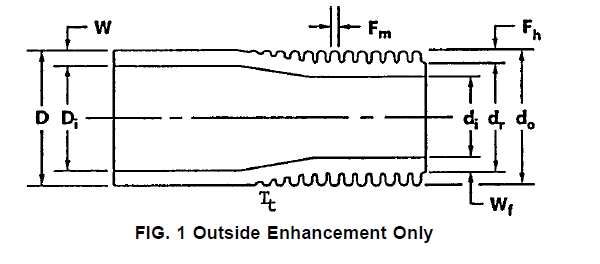
FIG. 1 Outside Enhancement Only
4.1 It is the responsibility of the purchaser to specify all requirements that are necessary for material ordered under this specification. Such requirements may include, but are not limited to, the following:
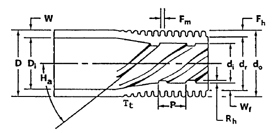
FIG. 2 Outside and Inside Enhancement
4.1.1 ASTM designation and year of issue (this specification);
4.1.2 ASTM designation and year of issue (plain tube specification);
4.1.3 Welded or seamless;
4.1.4 Alloy grade and UNS designation;
4.1.5 Dimensions; plain tube outside diameter, plain tube wall thickness (average or minimum specified), length and location of unenhanced surfaces and the total tube length. Configuration of enhanced surfaces (fins per unit length, fin height, wall thickness under fin, rib pitch, rib height, etc.) shall be as agreed upon between the manufacturer and purchaser (see Figs. 1 and 2).
4.1.6 Temper (as-finned or stress relief annealed);
4.1.7 Quantity;
4.1.8 Packaging;
4.1.9 Nondestructive tests;
4.1.10 Customer inspection;
4.1.11 Mill test report;
4.1.12 Certification.
5. ASTM A1012 General Requirements
5.1 Material furnished under this specification shall con- form to the applicable requirements of Specification A 450/ A 450M unless otherwise provided herein.
5.2 Enhanced (integrally finned) sections of the tube shall be produced by cold forming the tubing in such a manner that exterior fins, wall under the fin and inside ribs (when specified) are homogeneous.
5.3 Tubes described by this specification shall be furnished with unenhanced (plain) ends.
5.4 Enhanced sections of the tube are normally supplied in the “as finned” temper (cold worked condition produced by the enhancing operation). The unenhanced sections of the tube shall be in the annealed condition and shall be suitable for rolling-in operations.
6. ASTM A1012 Materials and Manufacture
6.1 The integrally enhanced (finned) tubes shall be manufactured from seamless, welded, or welded/cold worked plain tubes that conform to one of the following ASTM specifications: A 213/A 213M, A 249/A 249M, A 268/A 268M, A 269/ A 269M, A 688/A 688M, A 789/A 789M, A 803/A 803M.
7. ASTM A1012 Temper
7.1 The tube after enhancing shall normally be supplied in the as-finned temper. When specified by the purchaser, for bending, coiling or other fabricating operations, enhanced portions of the tube may be stress relief annealed or solution annealed.
7.2 Heat treatment of enhanced sections, or bend areas, or both, shall be in accordance with the governing plain tube specification.
8. ASTM A1012 Chemical Composition
8.1 The tubing specified shall conform to the chemical requirements prescribed in the governing plain tube specifica- tion.
9. ASTM A1012 Tensile Requirements
9.1 The tube prior to the finning operation, or unenhanced portions of the finned tube, shall conform to the requirements for tensile properties prescribed in the governing plain tube specification.
10. ASTM A1012 Permissible Variations in Dimensions
10.1 Diameter—The outside diameter of the unenhanced sections shall not exceed the diameter tolerances shown in the governing plain tube specification as measured by micrometers and verified by “go” and “no go” ring gages. The diameter over the enhanced sections shall not exceed the diameter of the plain sections involved, as determined by a “go” ring gage unless otherwise specified. The dimensions of the ring gages shall be as described in 10.1.1 and 10.1.2.
10.1.1 The inside diameter dimension of the “go” ring gage shall be equal to the nominal tube diameter, plus the maximum tolerance, plus .002 in. The length of the “go” ring gage shall be 1 in. (25.4 mm) minimum.
10.1.2 The inside diameter dimension of the “no go” ring gage shall be equal to the nominal tube diameter minus the maximum tolerance. The length of the “no go” ring gage shall be 1 in. (25.4 mm) minimum.
10.2 Wall Thickness—The wall thickness of enhanced and unenhanced sections shall not exceed the thickness tolerances shown in the governing plain tube specification unless other- wise agreed to between the manufacture and purchaser. No tube at any point shall be less than the minimum thickness specified in the plain sections or in the enhanced sections.
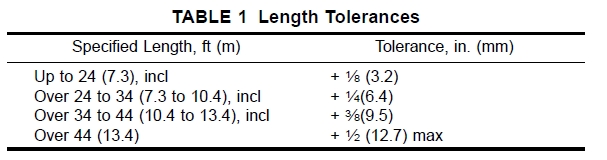
10.3 Length—The length of the tubes shall not be less than that specified, but may exceed the specified value by the amounts given in Table 1.
10.3.1 The length of plain ends, as measured from the tube end to the first tool impression, shall not be less than that specified, but may exceed the specified value by 1⁄2 in. (12.7 mm).
TABLE 1 Length Tolerances
Specified Length, ft (m) Tolerance, in. (mm) Up to 24 (7.3), incl + 1⁄8 (3.2)
Over 24 to 34 (7.3 to 10.4), incl + 1⁄4(6.4)
Over 34 to 44 (10.4 to 13.4), incl + 3⁄8(9.5)
Over 44 (13.4) + 1⁄2 (12.7) max
10.3.2 The length of fin sections and lands (unenhanced portions) shall be as specified 6 1⁄4 in. (6.35 mm).
10.4 Squareness of Cut—The angle of cut of the end of any tube may depart from square by not more than 0.016 in.
10.5 Straightness—The tube shall be reasonably straight and free of bends or kinks.
11. ASTM A1012 Workmanship, Finish and Appearance
11.1 Finished tubes shall be clean and free of foreign material, shall have smooth ends free of burrs, and shall be free of injurious external and internal imperfections. Minor defects may be removed, provided the dimensional tolerances of Section 10 are not exceeded.
11.2 A slight amount of oxidation on the surface resulting from heat treatment after enhancing or bending is acceptable. When the plain tube specification allows for a slight amount of oxidation on the surface resulting from heat treatment, this also is acceptable.
12. ASTM A1012 Nondestructive Tests
12.1 After enhancing operations, subject each tube to a nondestructive electromagnetic test, and either a pneumatic or hydrostatic test as specified in the purchase order. Tubes normally shall be tested in the as-fabricated condition but, at the option of the manufacturer or purchaser, may be tested in the stress relief annealed condition.
12.1.1 Eddy Current Test—Eddy current inspect the tube by passing it through an encircling coil designed to test the entire cross section of the tube.
12.1.1.1 The reference standard used to adjust the sensitivity setting of the apparatus shall be sound and of the same nominal alloy, enhanced configuration, condition (temper), and nominal dimensions as the lot of tubes to be tested on a production basis. Drill four holes not larger than 0.031 in. (0.787 mm) in diameter radially through the enhanced wall in each of four successive planes at 0°, 90°, 180°, and 270°. Use enhanced and unenhanced areas is not less than the minimum specified.
12.1.1.5 Tubes causing relevant signals because of injurious defects (incomplete welds, splits, embedded debris, broken tool impressions, ID defects), that reduce the wall thickness below the minimum specified shall be rejected. If, after retest and examination, no source for the reject signal can be discerned, the tube shall be rejected.
12.1.2 Pneumatic Test—When examined with this test method, each tube shall withstand a minimum internal air pressure of 250 psi (1.72 MPa), for a minimum of 5s, without showing evidence of leakage. The test method used shall permit easy detection of any leakage either by placing the tube underwater or by using the pressure differential method as follows:
12.1.2.1 Air Underwater Pressure Test—Each tube shall be tested in accordance with Specification A 450/A 450M except using test pressure specified in 12.1.2.
12.1.2.2 Pressure Differential Test—Procedure and acceptance criteria shall be agreed upon between the manufacturer and purchaser.
12.1.3 Hydrostatic Test—When examined with this test method, each tube shall be tested in accordance with Specification A 450/A 450M, except, the equation for calculating test pressure shall be modified as follows:
Inch2Pound Units: P 5 32 000 Wf / dr
SI Units: P 5 220.6 Wf / dr
where:
P = hydrostatic test pressure, psi (or MPa), Wf = wall under fin thickness, in. (or mm), dr = fin root diameter, in. (or mm),
12.1.3.1 As agreed upon between the manufacturer and purchaser, a minimum hydrostatic test pressure in excess of the requirements of Specification A 450/A 450M may be stated on the order. The tube wall stress shall be determined by the following equation:
a suitable drill jig to guide the drill, taking care to avoid distortion of the adjacent fins. Locate one hole in the weld for welded material. Space artificial discontinuities at least 16 in.
where: S 5 Pdr / 2Wf
(406 mm) apart to provide signal resolution adequate for interpretation. Discard and replace the reference standard when erroneous signals are produced from mechanical, metallurgical, or other damage to the tube.
12.1.1.2 Adjust the eddy current test unit to obtain an optimum signal-to-noise ratio with the minimum sensitivity required to detect all four artificial defects in the reference standard on a repeatable basis. Equipment adjustments and tube speed maintained during calibration shall be the same for production tubes.
12.1.1.3 Set aside tubes showing an eddy current indication in excess of any signal obtained from artificial defects in the reference standard and subject them to retest or rejection.
12.1.1.4 Tubes causing irrelevant signals because of debris and like effects shall be considered to conform, should they not cause output signals beyond acceptable limits when retested. Tubes causing irrelevant signals because of visible and identifiable handling marks (rough fin tip, notches in the fin) shall be considered to conform, provided the wall thickness in the
S = tube wall stress, psi (or MPa), and all other symbols as defined in 12.1.3.
12.1.3.2 The hydrostatic test may be performed before the tube is cut to final length but must be performed after enhancing, bending, heat treatment, or other forming operations.
13. ASTM A1012 Inspection
13.1 The manufacturer shall inspect and make the necessary tests to verify that the enhanced tubes furnished conform to the requirements of the customer purchase order and to the requirements of this specification.
13.2 Should the purchaser additionally elect to perform his own inspection, the manufacturer shall make provisions for such in accordance with requirements specified in Specification A 450/A 450M.
14. ASTM A1012 Rejection
14.1 Provisions for rejection shall be in accordance with requirements in Specification A 450/A 450M.
15. ASTM A1012 Certified Test Report
15.1 The manufacturer shall furnish to the purchaser a certified test report in accordance with requirements specified in A 450/A 450M.
15.2 In addition, the certified test report shall include the following information and test results, as modified, when applicable:
15.2.1 Plain Tube:
15.2.1.1 ASTM material designation.
15.2.1.2 Welded or seamless.
15.2.1.3 Alloy grade and UNS designation.
15.2.1.4 Tube dimensions (outside diameter and wall thick- ness).
15.2.1.5 Heat number.
15.2.1.6 Heat analysis.
15.2.1.7 Product analysis, when specified.
15.2.1.8 Tensile properties.
15.2.1.9 Flattening test acceptable.
15.2.1.10 Reverse flattening test acceptable.
15.2.1.11 Flaring test acceptable.
15.2.1.12 Flange test acceptable.
15.2.1.13 Hardness test values.
15.2.1.14 Hydrostatic or pneumatic test pressure and test results.
15.2.1.15 Non-destructive electric test method and test re- sults.
15.2.1.16 Impact test results.
15.2.1.17 Other test results or information required to be reported by the product specification.
15.2.1.18 Test results or information required to be reported by supplementary requirements, or other requirements desig- nated in the purchase order shall be reported, but may be reported in a separate document.
15.2.2 Enhanced Tube:
15.2.2.1 ASTM material designation.
15.2.2.2 Manufacturer name and order number.
15.2.2.3 Customer name and purchase order number.
15.2.2.4 Product description or part number.
15.2.2.5 Quantity.
15.2.2.6 Eddy current test results.
15.2.2.7 Pneumatic test pressure and test results, when specified.
15.2.2.8 Hydrostatic test pressure and test results, when specified.
15.2.2.9 Stress relief annealed, when specified.
15.2.2.10 Results of any other checks or testing required by the customer purchase order.
16. ASTM A1012 Packaging and Package Marking
16.1 The tube shall be packaged in accordance with the manufacturer’s standard practice, unless otherwise agreed upon between the manufacturer and the purchaser and so stated in the purchase order.
16.2 Each shipping unit shall be legibly marked with the name of the supplier, name of the customer, ship to address, purchase order number, alloy designation, size or part number, tube length and number of pieces.
17. ASTM A1012 Keywords
17.1 alloy steeel tube; austenitic stainless steel; carbon steel tube; condenser tube; duplex stainless steel; feedwater heater tubes; ferritic/austenitic stainless steel; ferritic stainless steel; heat exchanger tube; high temperature applications; seamless steel tube; stainless steel tube; steel tube; superheater tube; temperature service applications—high; welded steel tube
Standard ASTM A1012/A1012 download Links
UploadFiles/File/2023121013070872.pdf