


What Is a Copper Fin Tube and How Does It Work?
A copper fin tube is a heat transfer component made from a copper base tube with fins attached or integrally formed on its outer surface. The fins increase external surface area, which improves heat exchange between a fluid inside the tube and a gas or liquid flowing across the outside. Copper fin tubes are widely used in heat exchangers, condensers, air coolers, and heating coils where coppers thermal conductivity and corrosion resistance are valuable.
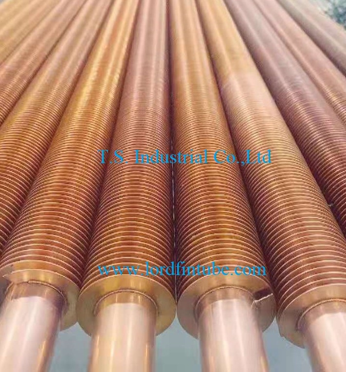
Core Definition: What Makes a Copper Fin Tube Different?
Copper fin tube definition: A tubular heat transfer element in which the tube and fins are copper-based, and the fins are either extruded from the tube wall, brazed or welded onto the tube, or wound around the tube. The base tube carries the internal fluid; the fins extend the external heat transfer area.
Primary function: Increase heat transfer surface area per unit length without proportionally increasing pressure drop or footprint.
Common base tube materials: Copper UNS C12200 (phosphorized copper) and C12000, with fin material matching the tube for extruded designs or selected for compatibility in brazed and wound designs.
The term copper fin tube covers several construction types. The most common industrial types are:
- Extruded copper fin tube: Fins are formed by extruding the tube wall outward, creating a metallurgical bond between fin and tube. No filler metal is used.
- Brazed copper fin tube: Pre-formed copper or copper alloy fins are brazed to the base tube. The bond depends on filler metal and process control.
- Wound copper fin tube: A copper strip is wound and tensioned onto the tube, sometimes with a separate bonding method. This type is common in specific HVAC and refrigeration coils.
- L-type copper fin tube: A tension-wound fin with an L-shaped root that covers the tube surface, often used where moderate corrosion protection and cost control are priorities.
Among these, the extruded type is often selected when the fin-to-tube bond integrity and long-term thermal performance are critical. The copper extruded finned tube construction eliminates the contact resistance associated with some mechanically attached fins, though it has manufacturing limits on fin height and base tube geometry.
Key Parameters and Units for Copper Fin Tubes
Specifying a copper fin tube requires more than stating the tube diameter. The following parameters determine thermal performance, pressure drop, mechanical strength, and manufacturability.
| Parameter | Symbol | Unit | Typical range | Engineering significance |
|---|---|---|---|---|
| Base tube outside diameter | Do | mm | 6–25 mm typical range | Sets internal flow area, tube-side pressure drop, and available fin height. |
| Base tube wall thickness | tw | mm | 0.5–1.5 mm typical range | Affects pressure rating, corrosion allowance, and fin extrusion feasibility. |
| Fin height | Hf | mm | 3–12 mm typical range | Increases external surface area; higher fins reduce fin efficiency and may raise fouling risk. |
| Fin thickness at root | tf | mm | 0.3–1.0 mm typical range | Controls fin efficiency, mechanical durability, and extrusion process limits. |
| Fin pitch / fin density | Pf or FPI | mm or fins per inch | 2–8 mm pitch; 3–12 FPI typical range | Balances area density against gas-side pressure drop and fouling tendency. |
| Fin efficiency | ηf | dimensionless | 0.6–0.95 typical range | Indicates how effectively the fin temperature approaches the tube surface temperature. |
| Overall heat transfer coefficient | U | W/(m²·K) | Application-specific | Depends on both tube-side and gas-side film coefficients; finned surface area is used as reference. |
| Design pressure | P | bar or MPa | Project-specific | Governs wall thickness and tube-to-tubesheet joint design. |
| Design temperature | T | °C | Project-specific | Affects material strength, thermal expansion, and brazing filler selection. |
Values above are typical ranges for general guidance. Final dimensions, tolerances, and performance values must be confirmed against project specifications, engineer approval, and manufacturer data. Do not use these ranges as a substitute for a thermal design calculation.
Formulas and Variables: How Is Fin Surface Area Calculated?
Copper fin tube performance depends on the extended surface area. A simplified calculation for the total external area per unit length of a uniformly finned tube is shown below. The formula is an engineering approximation; actual manufacturing geometry, fin root fillets, and fin tip shape will affect the exact value.
| Variable | Meaning | Unit |
|---|---|---|
| Atotal | Total external heat transfer area | m² |
| L | Tube length | m |
| Do | Base tube outside diameter | m |
| Hf | Fin height | m |
| tf | Fin thickness | m |
| Nf | Number of fins per unit length | 1/m |
The first term accounts for the exposed base tube surface between fins. The second term accounts for the two fin faces and the fin tip area. In practice, manufacturers may use different geometric assumptions for fin root and tip radii, so the calculated area can differ slightly between suppliers. Always use the manufacturers confirmed geometry for final thermal rating.
Fin Efficiency and the Biot Number
Fin efficiency is often estimated with the standard straight-fin relation:
Here, h is the gas-side heat transfer coefficient in W/(m²·K), k is the copper thermal conductivity in W/(m·K), tf is fin thickness in m, and Lf is an effective fin length in m. For copper, k is high relative to many alloys, which helps maintain fin efficiency at practical fin heights. However, the gas-side coefficient h often dominates, and a high fin can still have reduced efficiency if h is low.
Comparison: Extruded vs. Brazed vs. Wound Copper Fin Tubes
| Comparison dimension | Extruded copper fin tube | Brazed copper fin tube | Wound / L-type copper fin tube |
|---|---|---|---|
| Fin-to-tube bond | Integral, metallurgical bond formed by extrusion | Filler-metal bond; quality depends on brazing process | Mechanical contact, sometimes supplemented by tension or coating |
| Thermal contact resistance | Low, because fin and tube are one piece of metal | Low to moderate, depending on filler coverage | Higher risk of contact resistance if tension is lost |
| Fin height capability | Limited by extrusion ratio; moderate heights | Can accommodate taller fins | Flexible; often used for lower-cost coils |
| Corrosion behavior | All-copper surface; no dissimilar filler at fin root | Filler metal may create a galvanic couple in some environments | Exposed tube surface depends on fin foot coverage |
| Manufacturing cost | Higher tooling and process control cost | Moderate; depends on brazing method and inspection | Lower for simple geometries |
| Typical use | Heat exchangers requiring stable long-term thermal performance | Applications needing taller fins or specific alloy combinations | HVAC coils, refrigeration, and cost-sensitive units |
Selection between these constructions is not only a cost decision. The operating environment, cleaning method, thermal cycling, and required service life all influence which copper fin tube type is appropriate. For related constructions, see the L-type copper fin tube page and the broader copper finned tubes range.
Design Trade-offs: Fin Height, Fin Pitch, and Pressure Drop
Fin geometry involves coupled trade-offs. Increasing fin height raises external area, but it also lowers fin efficiency and can increase the gas-side pressure drop. Reducing fin pitch increases area density, but tighter spacing raises fouling risk and makes cleaning harder. Increasing fin thickness improves durability and fin efficiency, but it adds weight and material cost.
| Design change | Benefit | Penalty / risk | When to consider |
|---|---|---|---|
| Increase fin height | More external area per meter | Lower fin efficiency; higher pressure drop; larger envelope | Gas-side coefficient is low and space allows |
| Decrease fin pitch (more FPI) | Higher area density; smaller coil footprint | Higher fouling tendency; harder cleaning; higher pressure drop | Clean gas streams with predictable operation |
| Increase fin thickness | Better fin efficiency and mechanical robustness | More copper consumption; higher weight and cost | High-vibration or handling-sensitive applications |
| Increase base tube diameter | Lower tube-side pressure drop; more room for fin extrusion | Larger overall bundle; higher material cost | High tube-side flow or viscous fluids |
| Use extruded rather than wound fin | Stable thermal contact; no contact resistance | Higher initial cost; geometry limits | Long service life and thermal stability are priorities |
These trade-offs interact. For example, a tall fin with a tight pitch may appear to maximize area, but the combined effect of lower fin efficiency, higher pressure drop, and fouling can reduce net heat transfer. A balanced design is usually reached through iterative thermal and hydraulic calculation, not by maximizing a single parameter.
Technical Parameter Table: Typical Copper Fin Tube Specifications
| Specification item | Typical range / option | Confirmation required |
|---|---|---|
| Base tube material | Copper UNS C12200, C12000 | Material certificate and project specification |
| Fin material | Copper matching base tube; other copper alloys by agreement | Compatibility with process fluid and cleaning method |
| Base tube OD | 6–25 mm typical range | Thermal design and tube-side pressure drop calculation |
| Base tube wall | 0.5–1.5 mm typical range | Design pressure and corrosion allowance |
| Fin height | 3–12 mm typical range | Fin efficiency and envelope constraints |
| Fin pitch | 2–8 mm typical range | Gas-side fouling and cleaning strategy |
| Tube length | Up to several meters, project-specific | Handling, shipping, and heat exchanger layout |
| Fin type | Extruded, brazed, wound, L-type | Thermal duty, environment, and maintenance plan |
| End connection | Plain ends, expanded, welded, or per drawing | Tubesheet joint design and code requirements |
Materials and Standards
Copper fin tubes are commonly produced from phosphorized copper grades. The base tube and fin material selection must consider thermal conductivity, corrosion resistance, mechanical strength at temperature, and joining method.
- Base tube: Copper UNS C12200 is a common choice for heat exchanger and plumbing-related service. C12000 is also used where specified.
- Fin material: In extruded constructions, the fin is formed from the tube wall itself, so the fin chemistry matches the base tube. In brazed and wound constructions, the fin strip is selected for formability and compatibility with the base tube and environment.
- Standards: ASTM B111 covers copper and copper alloy seamless condenser and heat exchanger tubes. ASTM B359 covers copper and copper alloy finned tubes for condensers and heat exchangers. ASME SB-111 and SB-359 are the corresponding ASME specifications. Project specifications may also reference other national or customer standards.
Standards and material grades must be confirmed for each project. Not every supplier stocks every grade, and equivalence between standards is not automatic. The final material certificate, dimensional standard, and inspection scope should be agreed in the purchase order.
Application Industries for Copper Fin Tubes
Copper fin tubes are selected where coppers thermal conductivity and corrosion resistance provide an advantage, and where the external heat transfer coefficient benefits from extended surface.
- HVAC and refrigeration: Condensers, evaporators, air coolers, and heating coils.
- Power and process cooling: Aftercoolers, intercoolers, and fluid coolers.
- Industrial heating: Air heaters, convection heaters, and steam-to-air heat exchangers.
- Chemical and petrochemical: Solvent recovery, gas coolers, and hydrogen coolers where copper is compatible with the process stream.
- Food and pharmaceutical: Cleanable heat exchange surfaces where coppers properties are acceptable and cleaning regimens are compatible.
- Marine and offshore: Selected cooling and heat transfer duties where copper alloy resistance is suitable and the environment is assessed.
Copper is not universally corrosion-resistant. Ammonia, some sulfur compounds, and certain oxidizing environments can attack copper. Material compatibility must be reviewed by the process engineer before selection.
Selection Guide: Choosing the Right Copper Fin Tube
Use the following sequence to narrow the specification. The goal is not to select the largest surface area, but to find a geometry and construction that meet the thermal duty within pressure drop, fouling, and mechanical limits.
- Define the fluids and operating conditions. Record tube-side and gas-side flow rates, inlet and outlet temperatures, design pressure, design temperature, and allowable pressure drop.
- Confirm material compatibility. Check copper against both process fluids, cleaning chemicals, and any external atmosphere. Consider brazed filler metal if a brazed fin tube is proposed.
- Estimate the required external area. Use a preliminary overall heat transfer coefficient based on finned area, then refine with vendor data and detailed calculation.
- Select a fin geometry envelope. Choose fin height and pitch that balance area, fin efficiency, pressure drop, and fouling. Keep cleaning access in mind.
- Choose the fin construction. Compare extruded, brazed, and wound options against thermal stability, corrosion risk, cost, and lead time.
- Check mechanical design. Verify base tube wall thickness, tube-to-tubesheet joint, support spacing, and vibration risk.
- Define inspection and documentation. Agree on dimensional checks, hydrostatic or pneumatic testing, eddy current testing where applicable, and material certificates.
Quality and Inspection
Quality control for copper fin tubes focuses on dimensions, bond integrity, and pressure containment. The exact test plan depends on the project specification, but typical checks include:
| Inspection item | Purpose | Typical method |
|---|---|---|
| Base tube dimensional check | Confirm OD, wall thickness, and length | Micrometer, caliper, ultrasonic wall measurement |
| Fin geometry check | Confirm fin height, pitch, and thickness | Profile projection, optical measurement, or gauges |
| Fin bond assessment | Detect poor bonding or contact in brazed and wound designs | Visual inspection, bend test, or sectioning as specified |
| Pressure test | Verify tube integrity and joint tightness | Hydrostatic or pneumatic test per code and project specification |
| Non-destructive examination | Detect wall defects or seams | Eddy current test or other method when specified |
| Surface and cleanliness | Remove loose material and protect fin pack | Visual inspection and cleaning before packing |
| Material documentation | Trace base tube and fin material | Mill certificates and heat number correlation |
Specific test methods, acceptance criteria, and witness requirements must be agreed in the purchase order. This article does not claim that any particular test is universally performed.
Packaging and Shipping
Copper fin tubes are susceptible to fin damage during handling and transport. Packaging should protect the fin pack, prevent tube-to-tube abrasion, and keep the bore clean.
- Fin protection: Use cardboard, plastic sleeves, or wooden cradles to prevent fin crushing. Avoid direct metal-to-metal contact between fin packs.
- Bore protection: Cap or plug tube ends to keep out dust, moisture, and debris.
- Bundle support: Use timber or padded supports at intervals to prevent sagging and localized fin pressure.
- Moisture control: For sea freight, include desiccant and moisture-barrier wrapping where the project requires it.
- Marking: Label bundles with heat number, dimensions, quantity, and handling symbols.
Packaging requirements are project-specific. Heavy bundles, long tubes, and export routes may require additional protection or special lifting points. Confirm the packing method with the manufacturer before shipment.
Frequently Asked Questions
What is a copper fin tube?
A copper fin tube is a heat transfer tube with a copper base tube and copper fins on the outside. The fins increase external surface area so heat can move between the fluid inside the tube and the gas or liquid outside more effectively. Common constructions include extruded, brazed, and wound fins.
How is a copper fin tube manufactured?
The base copper tube is first formed to the required diameter and wall thickness. For extruded fin tubes, the outer wall is displaced outward into fins by an extrusion tool, creating an integral fin. For brazed fin tubes, pre-formed fins are joined to the tube with a filler metal. For wound fin tubes, a copper strip is wound and tensioned onto the tube. Each process has its own dimensional limits and quality controls.
What is the difference between extruded and brazed copper fin tubes?
Extruded copper fin tubes have fins formed from the tube wall itself, so the fin and tube are one continuous metal piece. This reduces thermal contact resistance. Brazed copper fin tubes use a filler metal to attach separate fins, which can allow taller fins and different alloy combinations but introduces a filler-metal interface that must be controlled for corrosion and thermal performance.
How do I calculate the heat transfer area of a copper fin tube?
Total external area per unit length is the sum of the exposed base tube area and the fin area, accounting for fin height, fin thickness, and fin pitch. The formula in this article provides a practical estimate. Final thermal rating must use the manufacturers confirmed geometry and the projects fluid properties, because fin root shape and tip geometry vary between suppliers.
What fin height and fin pitch should I select?
There is no single answer. Taller fins add area but reduce fin efficiency and can increase pressure drop. Tighter fin pitch adds area density but raises fouling risk and makes cleaning harder. Typical ranges for general guidance are 3–12 mm fin height and 2–8 mm fin pitch, but selection must be based on thermal calculation, pressure drop limits, fouling assessment, and cleaning method. Confirm the final geometry with the heat exchanger designer and manufacturer.
Which industries use copper fin tubes?
Copper fin tubes appear in HVAC and refrigeration coils, air coolers, condensers, evaporators, intercoolers, aftercoolers, air heaters, and process gas coolers. They are also used in solvent recovery, hydrogen coolers, and other heat exchange duties where copper is compatible with the process fluids. Compatibility with ammonia, sulfur compounds, and certain oxidizing media must be checked before use.
How are copper fin tubes tested for quality?
Typical inspection includes dimensional checks on the base tube and fin geometry, visual inspection, pressure testing, and material certificate review. Non-destructive examination such as eddy current testing may be specified. The exact test plan, acceptance criteria, and documentation package should be agreed in the purchase order and confirmed against the applicable standard.
What are typical packaging and shipping methods?
Copper fin tubes are usually shipped in bundles with fin protection, end caps, and moisture control as needed. Timber supports, padded separators, and clear handling marks help prevent fin damage. For export or long routes, desiccant and barrier wrapping may be added. The final packing method depends on tube length, bundle weight, transport mode, and project requirements.
Send your operating conditions, allowable pressure drop, and material requirements. Lordfintube will review the copper fin tube specification and respond with a technical proposal.
Request a Quote