

What is the Difference between Intercooler and Aftercooler
In industrial equipment such as turbocharged engines and air compression systems, thermal management directly determines the life and energy efficiency of the equipment. Aftercoolers and intercoolers are two key heat exchange devices, which are often confused due to their similar names. Here will systematically analyze the technical differences between the two from the principle, structure to application scenarios.
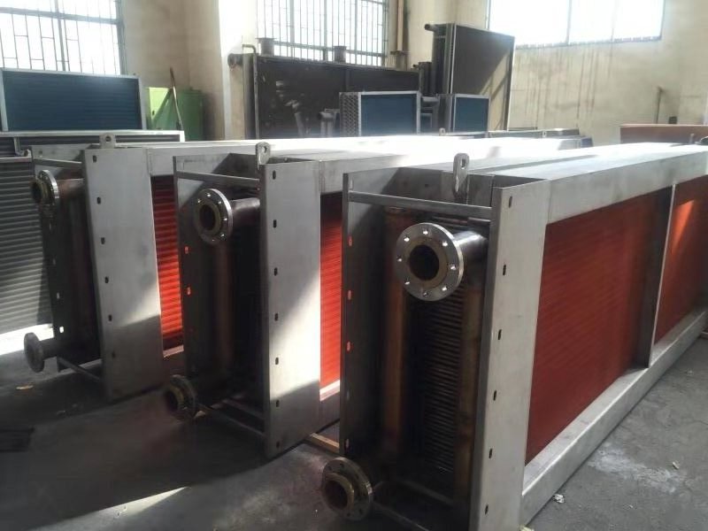
Typical applications of intercoolers and aftercoolers in industrial systems
Intercooler and Aftercooler Basic Concept Differences
Aftercooler
Definition: A heat sink installed at the outlet of the compressor to reduce the temperature of high-temperature compressed air.
Core Function: Prevent high-temperature gas from causing deformation of downstream pipelines, while removing moisture and oil from the air through condensation to improve air quality (such as in air compressor systems).
Intercooler
Definition: A heat exchanger in a turbocharged engine, located between the turbocharger and the engine intake manifold.
Core Function: Cools the intake air heated by the turbocharger, increases oxygen density to improve combustion efficiency, and reduces the risk of engine knock.
Detailed Comparison: Intercooler vs Aftercooler
| Comparison Items | Intercooler | Aftercooler |
|---|---|---|
| Core Function | Reduce the intake air temperature after turbocharging to improve combustion efficiency | Cool the compressed gas, remove moisture and oil to protect downstream equipment |
| Installation Location | Between the turbocharger and the engine intake manifold | Between the compressor outlet and the air receiver/pipeline |
| Cooling Medium | Air-cooled (common) or water-cooled (for high-efficiency scenarios) | Water-cooled (mainstream) or air-cooled (for small-sized equipment) |
| Temperature Treatment Range | Intake air temperature: 80-200°C → Cooled to 50-60°C | Compressed gas temperature: 120-200°C → Cooled to 40-50°C |
| Structural Features | Honeycomb-shaped heat dissipation channels with windward surface design | Multi-layer coil or plate-type heat dissipation, with built-in condensate water separation device |
| Key Target Objects | Engine intake air | Compressed air (or other industrial gases) |
| Application Fields | Automobiles (turbocharged engines), marine diesel engines, generator sets | Air compressor systems, refrigeration equipment, injection molding machines, pneumatic tools |
| Performance Indicators | Pressure drop (pressure loss), cooling efficiency | Dehumidification rate, corrosion resistance, condensate water discharge capacity |
| Maintenance Focus | Clean the dust on the heat sink fins and check the tightness | Prevent scale blockage and regularly drain the condensate water |
| Typical Industry Standards | SAE J1723 (Automotive Intercooler Test Specification) | ISO 7183 (Performance Standard for Compressed Air Aftercoolers) |
Intercooler Technical Analysis
Core Structure
- Intake housing and outlet housing: Connect the turbocharger (intake end) and the engine intake manifold (outlet end) respectively to form a flow channel for compressed air.
- Cooling water pipe and fins: Multiple aluminum cooling water pipes arranged in a dot matrix, with fins covering the surface to enhance heat dissipation efficiency. In improved designs, cooling water circulates through four processes to avoid dead corners.
- Cooling end plate and top plate: Structural parts supporting the cooling water pipe, with the top plate fixed by vertical bolts to enhance load-bearing capacity (such as when installing a supercharger).
- Filter and slow flow structure: Some designs include arc filters and slow flow plates in the intake pipe to filter impurities and adjust air flow speed to reduce impact damage.
Workflow Diagram
(Cooling medium: air cooling/water cooling)
Aftercooler Technical Analysis
Core Structure
- Multi-layer coil or plate radiator: Made of stainless steel or corrosion-resistant material, with built-in condensate separation device, used to cool and remove moisture and oil from compressed air.
- Inlet and outlet water end cover: Divided into water inlet chamber, water outlet chamber and reversing chamber, optimizes the cooling water flow path and improves dehumidification efficiency.
- Support frame and sealing structure: Usually integrated with the air compressor system, fixed to the compressor outlet by bolts to prevent high temperature gas from causing pipe deformation.
Workflow Diagram
(Cooling medium: mainly water cooling)
Intercooler and Aftercooler Typical Application Scenarios
1. Automotive Turbocharger System
(Cooling medium: air cooling/water cooling)
2. Industrial Air Compressor System
(Cooling medium: mainly water cooling)
Intercooler and Aftercooler
Introduce differences between intercoolers and aftercoolers in terms of core functions, structural characteristics, installation locations, and application areas. Intercoolers are primarily used in turbocharging systems to improve engine combustion efficiency, while aftercoolers are mainly employed in compressed air systems to protect downstream equipment and improve air quality.
Correctly understanding the differences between these two heat exchange devices is crucial for the design, selection, and maintenance of industrial equipment. We hope this article helps you make more accurate technical judgments and equipment choices in your practical work.