


A fin tube for fin fan cooler duty is the heat-transfer element that decides how much heat a forced-draft or induced-draft air cooler can reject inside a fixed plot space. The tube bundle, not the fan, usually sets the limit: once airflow and fan power are fixed, the only practical way to raise capacity is to increase the external surface area per metre of tube. That is exactly what a cooler finned tube does. This article explains how a fin fan cooler finned tube is specified, how the main geometry parameters interact, and which trade-offs matter when a designer moves from a bare tube to a fully finned surface.
What Is a Fin Tube for Fin Fan Cooler Service?
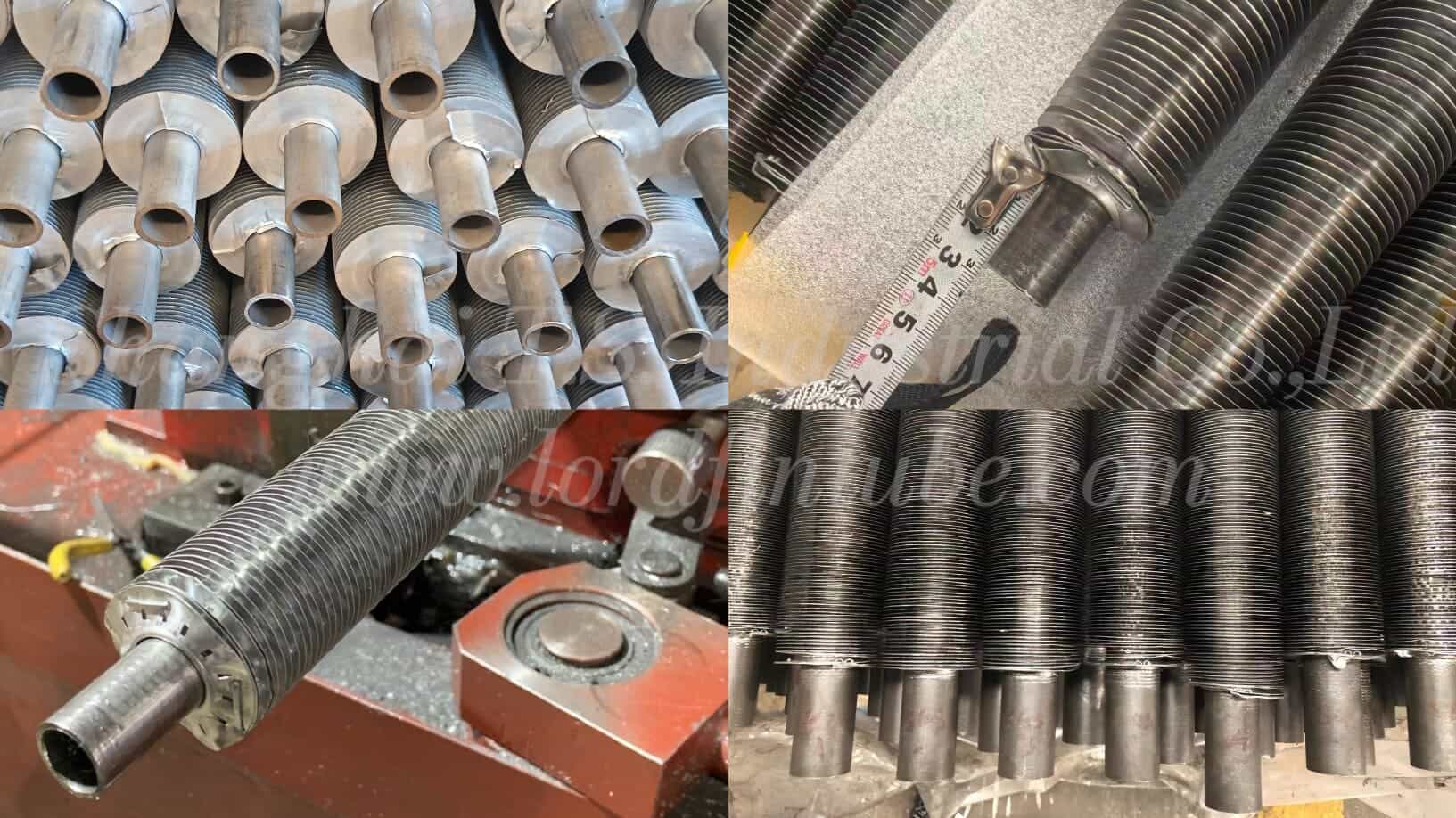
A fin tube for fin fan cooler service is a base tube — typically 12.7 mm to 38.1 mm outside diameter (typical range) — carrying a dense array of transverse fins on its outer surface, with bare tube ends left for tube-to-tubesheet joints. The finned section is the part exposed to the air stream; the bare ends are the part rolled or welded into the header.
For air-side heat transfer, the controlling resistance is almost always the gas film on the outside of the tube, because air has a low convective heat transfer coefficient compared with liquids or condensing vapours inside the tube. Adding fins multiplies the air-side area without changing the tube count, which raises the overall heat transfer coefficient referred to the bare tube area. Typical fin area ratios for cooling service fall between 8:1 and 25:1 (typical range), depending on fin height and fin density.
Where the cooler finned tube sits in the air cooler
- Tube bundle: rows of fin fan cooler finned tubes, usually staggered, connected to headers at both ends.
- Air side: forced or induced draft fans push or pull ambient air across the finned surface.
- Process side: liquid, gas, or condensing vapour flows inside the base tube.
- Support side: tubes pass through tube supports that also act as vibration control points.
How Does a Cooler Finned Tube Improve Heat Rejection?
Fins work by adding surface where the resistance is highest. If the air-side film coefficient is roughly one tenth of the tube-side coefficient, extending the air-side surface brings the two sides closer to balance. The result is a higher overall heat transfer rate per unit of tube length and, in most projects, a smaller bundle footprint.
The gain is not unlimited. Each additional fin also adds material, weight, and air-side pressure drop. Beyond a certain fin density, the boundary layers between adjacent fins merge and the incremental surface stops earning its keep. Fin efficiency falls as fin height rises, because the fin tip runs closer to air temperature than to tube wall temperature.
Key Parameters and Units for Fin Fan Cooler Finned Tube
The four parameters below drive thermal performance, mechanical integrity, and manufacturability at the same time. All values must be confirmed against project specification, engineer review, and manufacturer data before release to production.
| Parameter | Symbol | Typical unit | Why it matters |
|---|---|---|---|
| Fin density (fins per inch or fins per metre) | N | FPI, fins/m | Sets external surface area and air-side pressure drop |
| Fin height | H | mm | Controls area gain and fin efficiency |
| Fin thickness | t | mm | Controls fin stiffness, corrosion allowance, and contact quality |
| Base tube outside diameter | Do | mm | Sets tube-side area, tube count, and tube-to-tubesheet joint design |
Fin density (FPI)
Fin density is the number of fins counted along one inch or one metre of tube. Air cooler bundles commonly run at 8 to 11 FPI (typical range) for clean, dry air, and at lower densities — 4 to 7 FPI (typical range) — where dust, fibre, or condensable carryover can foul the surface. Higher density means more area, but also more pressure drop and faster fouling.
Fin height
Fin height is the radial distance from the base tube surface to the fin tip. Typical values sit between 6 mm and 16 mm (typical range). Tall fins add area cheaply on paper, but fin efficiency drops, and the outer portion of a tall fin may contribute little to the duty.
Fin thickness
Fin thickness is the plate thickness of the fin stock before forming. Typical values are 0.2 mm to 0.6 mm (typical range). Thin fins transfer heat well but dent easily during handling and cleaning; thicker fins survive high-pressure washdown and mildly corrosive air.
Base tube outside diameter
Base tube outside diameter sets the inside diameter available for process flow and the wall thickness available for pressure containment. Common air cooler sizes are 15.9 mm, 19.05 mm, 25.4 mm, and 31.8 mm (typical range). Larger tubes reduce tube count and pressure drop on the process side but need more space per row.
Formula: How to Calculate Finned Surface Area per Metre
Area calculations are the backbone of any air cooler thermal rating. The following relationships give the external surface per metre of finned tube for plain transverse (annular) fins. Different manufacturers and standards may count area slightly differently — for example including or excluding fin tip area, or treating the fin-to-tube contact zone separately — so never mix area definitions from two sources in one calculation.
Abare = π × Do × (1000 − N × t) × 10⁻⁶
Atotal = Afin + Abare
Fin ratio = Atotal / (π × Do × 10⁻³)
Variable definitions and units:
- N — fin density, fins per metre (1/m). Convert from FPI by multiplying by 39.37.
- Do — base tube outside diameter, mm.
- H — fin height, mm.
- t — fin thickness, mm.
- Afin — fin surface per metre of tube, m²/m.
- Abare — exposed base tube surface between fins per metre, m²/m.
- Atotal — total external surface per metre, m²/m.
The formula assumes a nominal fin density applied over the full 1,000 mm length and ignores fin tip area and any forming radius at the fin root. For a project specification, the area convention must be agreed in writing before the thermal design is frozen.
How fin density and fin height affect performance
Fin density and fin height both raise Atotal, but they do not behave identically. Increasing fin density adds area in a thin, well-coupled zone near the root, where fin efficiency is high, but it raises air-side pressure drop quickly. Increasing fin height adds area at the tip, where fin efficiency is lower. Fin thickness is the counterweight: a thicker fin conducts heat along the fin height more effectively and improves fin efficiency, but it also blocks flow between fins and reduces the free-flow area. A designer who raises density to gain area may need to lower height, or accept a larger fan, to stay within the allowable pressure drop.
Fin Type Comparison for Air Cooler Bundles
| Comparison dimension | Extruded aluminium fin | Embedded G fin | Wrap-on L / LL fin | Knurled / rolled fin |
|---|---|---|---|---|
| Typical service temperature (typical range) | Up to about 250 °C | Up to about 350 °C | Up to about 250 °C | Up to about 250 °C |
| Fin-to-tube contact | Integral, formed from the tube wall | Mechanically embedded in a groove | Mechanical wrap, tensioned | Mechanically rolled into the tube surface |
| Air-side area gain | Moderate to high | High | Moderate | Moderate |
| Fouling tendency | Low | Moderate | Low to moderate | Low to moderate |
| Best fit when | Air is clean and a bimetallic aluminium fin on steel or copper base tube is acceptable | Higher temperature duty needs firm fin-to-tube contact | Moderate duty with copper or steel base tubes | Mechanical bonding is required without a separate fin strip |
Design Trade-offs and Selection Trade-offs
Every fin fan cooler finned tube specification is a compromise. The main trade-offs are listed below. They describe how the parameters interact; the final engineering decision always belongs to the customers design engineer and the project specification.
- Area versus pressure drop. More fins mean more surface and more air-side resistance. Fan power rises with the cube of airflow, so an over-finned bundle can cost more in operating power than it saves in plot space.
- Fin efficiency versus fin height. Tall fins add area but run at lower efficiency. The useful limit depends on fin material conductivity, fin thickness, and the air-side coefficient.
- Fin density versus fouling. Tight fin spacing performs well in clean air and poorly in dusty or fibrous service. Cleaning access should be considered at the design stage, not after commissioning.
- Material cost versus corrosion life. Aluminium fins are light and economical; stainless steel or titanium fins cost more but survive aggressive atmospheres and wet operation.
- Tube diameter versus tube count. Smaller tubes give more surface per unit volume but raise the number of tube-to-tubesheet joints and the risk of vibration.
- Weight versus structural cost. Fin material, tube wall thickness, and header size all feed into bundle weight, which drives the support structure and the fan bridge design.
Technical Specifications
| Item | Typical range / option |
|---|---|
| Base tube outside diameter | 12.7 mm – 38.1 mm |
| Base tube wall thickness | 1.2 mm – 3.0 mm, or as required for design pressure |
| Fin height | 6 mm – 16 mm |
| Fin thickness | 0.2 mm – 0.6 mm |
| Fin density | 4 – 11 FPI (approximately 157 – 433 fins/m) |
| Finned length | Up to 12 m per tube, subject to handling and transport limits |
| Fin type | Extruded, embedded G, wrap-on L / LL, knurled, or as specified |
| Tube ends | Bare ends for rolling, welding, or ferrule joints |
Materials and Standards
Material selection follows the process fluid, the design temperature, and the site atmosphere. The table below shows commonly used combinations; the final choice belongs to the project specification.
- Base tube: carbon steel, stainless steel (austenitic grades), copper alloys, titanium, and other corrosion-resistant alloys (typical range).
- Fin stock: aluminium and aluminium alloys, copper, stainless steel, and titanium (typical range).
- Finned tube construction: bimetallic (aluminium fin on steel or copper base tube), integral extruded, or solid alloy.
Standards: according to project specification or applicable standard to be confirmed. Do not assume that a material combination acceptable under one project specification is acceptable under another; tube dimensions, tolerances, inspection levels, and joint details are frequently project-specific.
Application Industries
Cooler finned tubes appear wherever air is the available cooling medium. Typical applications include:
- Oil and gas processing — gas cooling, compressor intercoolers and aftercoolers.
- Petrochemical and chemical plants — process condensers, overhead coolers, and reboiler air coolers.
- Power generation — turbine exhaust steam condensing, closed cooling water circuits.
- HVAC and refrigeration — condensers and fluid coolers.
- Compressed air and nitrogen systems — aftercoolers and dryers.
- Steel, cement, and glass — cooling of flue gas and process air.
- Renewable and waste-to-energy plants — exhaust and flue gas cooling.
Specification Data Required for Custom Manufacturing
Lordfintube is a custom manufacturer. The company does not carry out thermal rating, fan selection, bundle layout, or equipment selection on behalf of customers. To start a custom production order, the following information must be supplied by the customer or the customers design engineer.
- Base tube data. Outside diameter, wall thickness, length, material grade, and any tolerance requirements.
- Fin data. Fin type, fin density, fin height, fin thickness, and fin material.
- Finned length and bare end length. The exact finned section and the bare end dimensions required for the tube-to-tubesheet joint.
- Joint method. Rolling, welding, or ferrule, together with the applicable joint specification.
- Design conditions. Design pressure, design temperature, and the process fluid, so that the correct wall thickness and material can be confirmed.
- Air-side environment. Ambient conditions, dust, salt, or corrosive gases that affect fin material and fin density.
- Inspection and documentation requirements. Test scope, material certificates, and any third-party inspection requirement.
- Packing and transport constraints. Maximum bundle or tube length, lifting limits, and destination port.
Drawings or a written specification are preferred. Where a dimension or standard is not stated, production cannot begin until it is confirmed in writing.
Quality Control and Inspection
Inspection scope is agreed with the customer and stated in the project specification. Typical checks include:
- Base tube dimensional inspection — outside diameter, wall thickness, length, straightness.
- Fin dimensional inspection — fin density, fin height, fin thickness, finned length.
- Fin-to-tube contact check, where required by the specification.
- Visual examination of finned surface for damage, burrs, or loose fins.
- Bare end inspection and tube-to-tubesheet joint qualification by the applicable procedure.
- Hydrostatic or pneumatic pressure test of the assembled bundle, as specified.
- Material traceability and certificate review.
- Surface protection and cleanliness check before packing.
The exact test list, acceptance criteria, and sampling level are to be confirmed against the project specification and the applicable standard.
Packing and Shipping
Finned tube and assembled bundles are easily damaged in transit, so packing is a technical requirement rather than a formality. Typical practice includes:
- Individual finned tubes separated by protective layers or sleeved at the finned section.
- Bare ends protected with caps or wraps to preserve joint surfaces.
- Bundles braced inside a steel-framed crate or on saddles to prevent movement.
- Moisture protection for long sea voyages, including desiccant and sealed wrapping where specified.
- Lifting points marked, and the crate marked with centre of gravity and orientation.
- Documentation pack — packing list, material certificates, and inspection records — matched to the shipment.
Final packing method, stacking limits, and transport configuration are to be confirmed against the project specification and the agreed shipping route.
FAQ
What is a fin tube for fin fan cooler service?
A fin tube for fin fan cooler service is a base tube with transverse fins on its outer surface, used in air-cooled heat exchangers where forced or induced air removes heat from the process fluid. Bare tube ends remain for the tube-to-tubesheet joint.
Does Lordfintube provide selection or thermal design services?
No. Lordfintube is a custom manufacturer of finned tube and air cooler finned tube. The company produces to customer-supplied specifications, drawings, and engineering data, and does not perform thermal rating, fan selection, or equipment selection.
How does fin density affect air cooler performance?
Higher fin density increases external surface area per metre of tube, which raises heat rejection for a given bundle size. It also increases air-side pressure drop and fouling risk, so the optimum density depends on how clean the air is and how much fan power is acceptable.
How do I calculate the finned surface area per metre?
Add the fin area to the exposed base tube area between fins. For annular fins, multiply two fin faces by the fin density and the annular area, then add the exposed base tube circumference multiplied by the free tube length between fins. Confirm the area convention with the specification before using the result in a rating.
Which fin materials are available for custom production?
Common combinations include aluminium fins on steel or copper base tubes, copper fins on copper tubes, and stainless steel or titanium fins where corrosion or higher temperature demands it. The final choice must be stated in the customers specification.
What typical fin height and thickness are used in air coolers?
Typical fin height is 6 mm to 16 mm and typical fin thickness is 0.2 mm to 0.6 mm. These are typical ranges only — final values depend on the customers specification and the confirmed manufacturing data.
How is a cooler finned tube inspected before shipment?
Inspection normally covers base tube dimensions, fin dimensions, fin-to-tube contact, visual condition of the finned surface, bare end condition, and pressure testing of the assembled bundle where specified. The exact scope is defined in the project specification.
Ready to place a custom finned tube order? Send your base tube data, fin geometry, material grades, joint method, inspection scope, and packing requirements. Lordfintube will review the specification and return a manufacturing quotation.
Request a Quote