


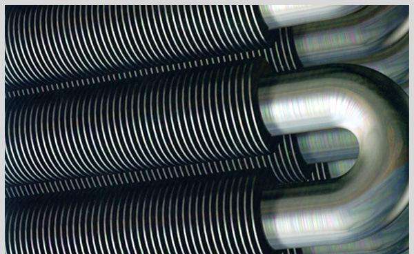
Finned tube with return bend is the component that turns a straight, finned heat-transfer tube into a continuous multi-pass coil. Instead of joining two tube ends with a separate fitting, the tube itself — or a matching 180° fitting — is bent so the flow reverses direction and travels back through the bundle. For engineers laying out a fired heater, air cooler, or waste-heat recovery unit, this single detail decides how many passes fit inside the casing, how much pressure drop the circuit carries, and how easily the coil can be cleaned.
What Is a Finned Tube with Return Bend?
Short answer: it is a finned tube whose ends are joined by a 180° bend — either an integral bend formed from the bare tube end or a welded return bend fitting — so that two parallel tube legs form one continuous flow path.
The finned section carries the extended surface that improves gas-side heat transfer. The return bend sits at the end of the coil, usually outside the finned zone, and connects leg one to leg two. Because the bend is bare (unfinned), it is normally positioned beyond the tube sheet or outside the gas path so it does not disturb the fin density or block cleaning lanes.
Two construction routes are common:
- Integral bending — the bare tube end is heated and drawn into a U. No circumferential weld exists in the bend, which suits carbon steel and low-alloy tubes where the bend can be formed and heat treated.
- Welded return bend — a prefabricated 180° fitting is butt-welded to each finned tube end. This is typical for stainless and high-alloy grades, or when the centre-to-centre distance is too tight to bend in one piece.
Both routes are covered in our serpentine finned tube range, which is built to match the pass arrangement of the exchanger.
How Does a Return Bend Work in a Heat Exchanger?
The return bend sets the flow path. Fluid enters the first tube leg, travels the full heated length, reverses 180° at the bend, and returns along the second leg. Repeating this pattern produces a serpentine coil with as many passes as the thermal duty requires.
Why does this matter thermally? A single straight pass usually cannot absorb the required duty within a practical casing length. Adding passes increases residence time and total surface area without increasing the footprint. The trade-off is hydraulic: every additional pass adds friction loss, so the bend radius and internal diameter must be chosen so the circuit still meets the allowable pressure drop.
Mechanically, the bend is also the most highly stressed point in the circuit. Bending strains the outer wall in tension and the inner wall in compression, and the bend must tolerate thermal expansion as the coil heats and cools. That is why bend radius, wall thickness after forming, and ovality are specified rather than left to the fabricator.
Specifications to Check
The table below lists ranges that are typical for industrial finned tube coils. Actual values must be confirmed against the project datasheet and the applicable code.
| Parameter | Typical range | Why it matters |
|---|---|---|
| Tube outside diameter | 1.0" – 6.0" (25.4 – 152 mm) | Sets flow area, bend tooling, and fin height limit |
| Wall thickness / schedule | Sch 40 – Sch 160, or 1.6 – 12 mm | Governs pressure rating and thinning allowance at the bend |
| Return bend centre-to-centre | 1.5 × OD to 3 × OD | Fixes tube pitch and bundle width |
| Bend radius (centreline) | 1.5 × OD (short) to 5 × OD (long) | Controls pressure drop, ovality, and wall thinning |
| Bend angle | 180° (standard); 90° for end connections | Defines pass pattern |
| Fin type | Extruded, L-foot tension wound, welded, solid, serrated | Affects heat transfer and fouling resistance |
| Fin height | 6 – 25 mm | Higher fins add area but raise gas-side pressure drop |
| Fins per inch (FPI) | 4 – 12 FPI | Higher density suits clean gas; lower density suits dirty service |
| Tube length | Up to approx. 30 m per leg, project dependent | Determines number of bends and shipping split |
| Design temperature | Up to approx. 650 °C for alloy grades | Drives material and heat treatment selection |
| Design pressure | Project specific, per ASME VIII / EN 13445 | Sets wall thickness and weld examination level |
Materials and Standards
Material choice follows the corrosive environment and the metal temperature at the bend, which is often the hottest, least-cooled part of the coil.
- Carbon steel — ASTM A106 / A179 / A192 for tubes, ASTM A234 WPB for return bends. Used for non-corrosive, moderate-temperature service such as steam and hot oil.
- Low-alloy and alloy steel — ASTM A213 T11, T22, T9 and ASTM A335 P11, P22, P9, with matching ASTM A234 WP grades for bends. Common in refinery fired heaters and reformer service.
- Stainless steel — ASTM A213 TP304/304L, TP316/316L, TP321, TP347; bends to ASTM A403 WP grades. Selected for corrosive flue gas or high-temperature oxidation resistance.
- Copper alloys — ASTM B111 C70600 (90/10 Cu-Ni), C71500 (70/30 Cu-Ni), and C12200 copper, used in marine, desalination, and refrigeration coils where seawater or brine is the cooling medium.
- Other grades — duplex and super duplex stainless, Inconel, Incoloy, and titanium are available on request for severe duty.
Governing documents normally referenced in a purchase specification include ASME Boiler and Pressure Vessel Code Section VIII for the pressure envelope, ASME B31.3 or B31.1 for piping, ASME B16.9 for buttweld fitting dimensions, ASTM A234 / A403 for wrought return bends, TEMA for shell-and-tube exchanger mechanical requirements, and API 560 / ISO 13705 for fired heater tubes. Welding and welder qualification generally follow ASME Section IX, with examination to Section VIII or B31.3 as applicable. Lordfintube operates under an ISO 9001:2015 quality management system.
Return Bend vs U-Bend
In day-to-day conversation the terms overlap, but in a specification they are not always identical. A U-bend is any 180° reversal. A return bend is the fitting or formed end used to close a pass pair in a heat exchanger coil, and in some codes the term carries a specific fitting specification. Confirm with the supplier which meaning applies to your datasheet.
| Point of comparison | Return bend | U-bend |
|---|---|---|
| General definition | 180° fitting or formed end joining two adjacent tube legs of a coil | Broad term for any 180° reversal in a tube or pipe |
| Typical application | Finned tube coils, fired heaters, air coolers, economizers | Shell-and-tube U-tube bundles, steam traps, general piping |
| Fins on the bend | Normally bare; finning stops before the bend | Normally bare |
| Standard reference | ASTM A234 / A403, ASME B16.9, API 560 | Project specification; often covered by tube-bundle design rules |
| Centre distance | Fixed by tube pitch of the coil; can be tight (from ~1.5 × OD) | Set by bundle tube pitch, often more generous |
| Construction | Integral bend or welded fitting | Usually integral bend in the tube, no weld |
| Repairability | Welded bends can be cut and replaced individually | Damage usually requires tube or bundle replacement |
| Pressure-drop behaviour | Influenced by bend radius and internal bore after forming | Similar, driven by bend radius and bore |
How to Select the Right Return Bend Finned Tube
- Fix the thermal duty and flow rate. Confirm heat load, mass flow, and allowable pressure drop. These decide the number of passes and whether a short or long radius bend is acceptable.
- Choose the tube material. Match the tube and return bend grades to the fluid, the metal temperature, and the corrosion mechanism. Keep tube and bend metallurgy compatible for welding.
- Set the tube OD and wall thickness. Size for velocity and pressure rating, then add a thinning allowance for the bend. Thin walls and tight radii are a poor combination.
- Select the bend radius. Short radius (around 1.5 × OD) saves space and suits tight bundles; long radius (2.5–5 × OD) reduces pressure drop, ovality, and wall thinning, and is easier to inspect.
- Set the centre-to-centre distance. This must align with the finned section pitch and clear the fins on both legs. Verify that the outside of the bend does not clash with the casing or header.
- Decide integral bend or welded fitting. Integral bending removes a weld but demands bendable material and adequate space. Welded return bends give more freedom on grade and geometry.
- Specify the fin configuration. Choose fin type, height, thickness, and FPI to balance heat transfer against fouling and draft loss.
- Define inspection and documentation. State weld examination, pressure test, NDT methods, heat treatment, and whether a material test report and dimensional record are required.
If you are weighing options for a specific coil layout, the team can review your pass arrangement against our serpentine finned tube configurations and confirm feasibility before quotation.
Design and Manufacturing Considerations
- Bend radius. As a rule of thumb, tighter radii increase wall thinning and ovality. Where pressure drop and inspectability matter more than space, specify a longer radius.
- Wall thickness reduction. Forming thins the outer wall of the bend. The minimum wall after bending — not the nominal wall — should be checked against the pressure design.
- Ovality. A flattened bend reduces the bore, raising pressure drop and creating a pigging or cleaning obstruction. Ovality limits should be stated in the specification.
- Heat treatment. Carbon and low-alloy bends may require stress relief after forming. Austenitic stainless grades may need solution annealing where sensitisation is a risk.
- Non-destructive examination. Welded return bends are typically examined by radiography or ultrasonic testing, with dye penetrant or magnetic particle testing on the root and cap as specified.
- Fin termination. Fins must stop clear of the weld or bend tangent line so the bend can be formed or welded and later inspected.
- Cleanliness. Bends should be free of scale, swarf, and forming lubricant. Internal cleanliness matters for oxygen service and for downstream catalysts.
- Dimensional control. Centre-to-centre distance, bend angle, and leg length tolerances must be held so the coil fits the casing without forced alignment.
Quality Inspection and Testing
Under an ISO 9001:2015 quality management system, a typical inspection sequence for a finned tube with return bend covers:
- Incoming material verification against the mill certificate, including heat number traceability.
- Dimensional checks on tube OD, wall thickness, fin height, fin pitch, and finned length.
- Bend geometry checks — radius, angle, centre-to-centre distance, ovality, and minimum wall after forming.
- Weld visual inspection and, where specified, radiography or ultrasonic examination of butt welds.
- Surface examination by dye penetrant or magnetic particle testing on welds and bend extrados.
- Hydrostatic or pneumatic pressure testing of the completed coil, with an air-under-water test where a leak check on finned assemblies is required.
- Post-test drying, internal cleaning, and end protection.
- Final documentation package: material test reports, NDT reports, pressure test certificate, heat treatment records, and dimensional report.
Packing and Shipping
Finned coils are fragile at the fins and at the bend tangents, so packing is designed around those two points.
- Tube ends and return bends are capped or plugged to keep out moisture and debris.
- Coils are braced in a steel frame or wooden cradle so the bends carry no unsupported load.
- Fin packs are protected with boards, strapping, or shrink film to prevent fin deformation in transit.
- Desiccant is added inside the packing where sea freight and condensation are expected.
- Lifting points and centre-of-gravity marks are shown on the crate; a packing list, and where applicable a certificate of origin, accompanies the shipment.
- Export packing is typically seaworthy, with the option of fumigation-free timber on request.
FAQ
What is a finned tube with return bend used for?
It is used to build multi-pass serpentine coils for heat exchangers, fired heaters, air coolers, economisers, and waste-heat recovery units, where fluid must reverse direction and travel back through the bundle.
What is the difference between a return bend and a U-bend?
A U-bend is a general term for any 180° reversal. A return bend is the specific fitting or formed tube end used to close a pass pair in a coil, and it is usually tied to a fitting specification such as ASTM A234 or A403. See the comparison table above for details.
How do I choose the return bend radius?
Balance space against hydraulics. Short radii around 1.5 × OD save bundle width but increase pressure drop and wall thinning. Long radii of 2.5–5 × OD reduce losses and are easier to inspect. Always check the minimum wall after forming against the pressure design.
Can the return bend be finned?
Return bends are normally left bare. Finning a bend is impractical and would obstruct forming, welding, inspection, and cleaning, so the finned length ends before the bend tangent.
Which materials are available for return bend finned tubes?
Carbon steel, low-alloy and alloy steel such as T11, T22 and P22, austenitic stainless steels, copper-nickel alloys, and, on request, duplex stainless, nickel alloys, and titanium. Tube and bend grades are matched for weldability.
What standards apply?
Commonly referenced documents include ASME Section VIII, ASME B31.3 or B31.1, ASME B16.9, ASTM A213 / A335 for tubes, ASTM A234 / A403 for return bends, TEMA for shell-and-tube exchangers, and API 560 / ISO 13705 for fired heaters.
How is the bend checked for quality?
Typical checks include dimensional and ovality measurement, minimum wall measurement after forming, visual and dye penetrant inspection, radiographic or ultrasonic examination of welds where specified, and hydrostatic or pneumatic pressure testing of the finished coil.
Can finned tubes with return bends be repaired in the field?
Welded return bends can often be cut out and replaced individually if the surrounding fins and tube ends allow access. Integrally bent tubes usually require section replacement. The practical answer depends on bundle access and the original weld procedure.
Request a Quote
Send your datasheet — tube OD, wall thickness, material grade, fin type, FPI, bend radius, centre-to-centre distance, pass arrangement, and design pressure and temperature — and Lordfintube will confirm feasibility and lead time.
Email: sales@lordfintube.com
Product page: Serpentine finned tubes with return bends
Please include the applicable code and any inspection or documentation requirements so the quotation reflects the full scope.