Products Description
Floating Head Heat Exchanger
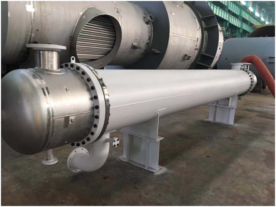
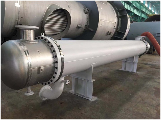
A floating head heat exchanger is a type of heat exchanger where only one end of the tube sheet is fixed to the shell, while the other end is free to move relative to the shell, known as the floating head. The floating head consists of a floating tube sheet, a hook ring, and a floating head end cover. It is detachable, allowing the tube bundle to be pulled out from the shell. The thermal deformation between the tube bundle and the shell is not constrained, preventing the generation of thermal stress. Its advantages include easy cleaning between tubes and inside tubes without thermal stress. However, its structure is complex, it has a higher cost compared to fixed tube sheet heat exchangers, the equipment is bulky, there is a high material consumption, and the inspection of the small cover on the floating head end is not possible during operation. High sealing requirements are needed during manufacturing. It is suitable for applications where there is a significant temperature difference between the shell and tube bundle or where scaling of the shell-side medium is likely.
Table of Contents
1. Introduction
2. Structure
3. Design Requirements
4. Pros and Cons
▪ Pros
▪ Cons
5. Manufacturing Process
6. Quality Inspection
7. Features
8. Faults and Countermeasures
Floating Head Heat Exchanger Introduction
In a floating head heat exchanger, one end of the tube sheet is fixed between the shell and the tube box, while the other end, called the floating head, can move freely within the shell. The tube bundle, along with the floating head, can expand and contract axially when heated, completely eliminating thermal differential stress.
Floating Head Heat Exchanger Structure
Drill holes between concave and trapezoidal grooves and thread or weld several evenly distributed screws. The floating head flange is concave and trapezoidal for double-sealing, and baffle plates and trapezoidal projections communicate with each other and are located on the wide flange at the same end face. The concave and trapezoidal projections, as well as the baffle plates, correspondingly match with the concave and trapezoidal grooves on the floating head tube sheet. The flange with no folded spherical head is welded to the floating head cover, and its flange screw holes are matched with the threaded holes or screws of the floating head tube sheet. Bolts or nuts are used to fasten and tighten the concave and trapezoidal grooves, as well as the baffle plate grooves and their gaskets. When necessary, the thickness and diameter of the floating head tube sheet can be appropriately increased, along with corresponding changes in the dimensions of related components. Additionally, an external force-assisted steel ring is configured, with its inner diameter larger than the outer diameter of the floating head tube sheet. One end of the steel ring is flanged and connected to the inner side of the concave or trapezoidal sealing surface on the outer head flange, while the other end is flanged or connected to the original concave groove and its gasket or outer circular seal on the floating head tube sheet.
Floating Head Heat Exchanger Design Requirements
With the development of the economy, various types and forms of heat exchangers have rapidly emerged. Standards have been established in China for certain types of heat exchangers to meet the growing needs, forming a series. A well-designed heat exchanger should meet the following basic requirements:
1. Reasonably achieve the specified process conditions.
2. Structurally safe and reliable.
3. Easy to manufacture, install, operate, and maintain.
4. Economically reasonable.
One end of the tube sheet in a floating head heat exchanger is fixed to the shell, while the other end is free to move within the shell. Therefore, when there is a significant temperature difference between the two media, thermal differential stress is not generated between the tube bundle and the shell. The floating head end is designed to be detachable, allowing for easy insertion or extraction of the tube bundle from the shell (can also be designed as non-detachable). This provides convenience for inspection and cleaning. However, the structure of this heat exchanger is complex, and the small cover on the floating end is not visible during operation, making sealing particularly important during installation.
Floating Head Heat Exchanger Structure, especially the floating head part, can be designed in various forms according to different requirements. In addition to ensuring that the tube bundle can move freely within the equipment, convenience for inspection, installation, and cleaning of the floating head part must also be considered.
In the design process, the outer diameter (Do) of the floating head tube sheet must be considered. This diameter should be smaller than the inner diameter (Di) of the shell. A recommended gap (b1) between the floating head tube sheet and the inner wall of the shell is generally 3-5mm. This allows the tube bundle to be pulled out of the shell after removing the hook ring, facilitating inspection and cleaning. Assembly of the floating head cover can only take place after the tube bundle is inserted, so the necessary space for the floating head cover during assembly should be considered in the design.
The hook ring plays a crucial role in ensuring the sealing of the floating head end and preventing leakage between media. With advancements in the design and manufacturing technology of floating head heat exchangers and the accumulation of long-term usage experience, the structure of the hook ring has been continuously improved and perfected.
The hook ring is generally of an open structure, requiring reliable sealing, simple and compact structure, and ease of manufacturing and disassembly.
Floating head heat exchangers, with their high reliability and wide adaptability, have accumulated rich experience during long-term use, continuously promoting their own development. Thus, they continue to dominate among various types of heat exchangers.
Floating Head Heat Exchanger Pros and Cons
Floating Head Heat Exchanger Pros:
1. The tube bundle can be pulled out for easy cleaning of tube and shell sides.
2. Not restricted by temperature differences between media.
3. Can operate at high temperatures and pressures, generally up to 450 degrees Celsius and 6.4 MPa.
4. Suitable for applications where scaling is severe.
5. Applicable in situations where the tube side is prone to corrosion.
Floating Head Heat Exchanger Cons:
1. Small floating heads are prone to internal leakage.
2. High metal material consumption, with a cost 20% higher.
3. Complex structure.
Floating Head Heat Exchanger Manufacturing Process
The manufacturing process of heat exchange equipment involves the selection and testing of materials, chemical composition testing, and mechanical performance testing. After ensuring the steel plates chemical composition and mechanical properties meet the requirements, the
plate undergoes straightening using methods such as manual straightening, mechanical straightening, and flame straightening.
Material preparation – Marking – Cutting – Edge processing (inspection for flaws) – Forming – Pairing – Welding – Weld quality inspection – Assembly welding – Pressure testing
Floating Head Heat Exchanger Quality Inspection
Chemical equipment undergoes material inspections not only before manufacturing but also at various stages during the manufacturing process.
Floating Head Heat Exchanger Features
One end of the tube sheet in a floating head heat exchanger is fixed between the shell and the tube box, while the other end of the tube sheet can move freely within the shell. This characteristic is visible in the field. The thermal expansion between the shell and the tube bundle is free, and the tube bundle can be pulled out for easy cleaning between tubes and inside tubes. The disadvantage is that the structure is complex, and the cost is higher (20% higher than fixed tube sheet heat exchangers). Leakage at the floating head during operation is not easy to detect. The floating head heat exchanger is suitable for conditions where there is a significant temperature difference between the shell and tube bundle or where the shell-side medium is prone to scaling.
Floating Head Heat Exchanger Faults and Countermeasures
In the production process, due to the flushing of the tube sheet in the floating head heat exchanger by water, cavitation, and corrosion of trace chemical media, leaks often occur at the weld seams of the tube sheet. This leads to the mixing of water and chemical materials, making it difficult to control the production process temperature and resulting in the production of other products, significantly affecting product quality and reducing product grades. After leaks occur at the tube sheet weld seams of the condenser, enterprises usually use traditional welding methods for repair. Internal stresses are easily generated in the tube sheet, and they are difficult to eliminate, causing leaks in other heat exchangers. Enterprises use pressing, inspecting equipment repair conditions, repeatedly welding, experimenting, and it takes several days for 2 to 4 people to complete the repair. After a few months of use, corrosion occurs again at the tube sheet weld seams, leading to wasted manpower, materials, and finances, increasing production costs. By using high molecular composite materials for corrosion resistance and erosion resistance, and by protecting new heat exchangers in advance, not only are welding and sanding issues effectively addressed, but chemical corrosion of heat exchanger metal surfaces and weld points is also avoided during subsequent periodic maintenance. Even if leaks occur after use, they can be repaired in a timely manner using technology, avoiding long-term welding repairs that affect production. It is this fine management that greatly reduces the probability of heat exchanger leaks, not only reducing equipment procurement costs but also ensuring product quality, production time, and increasing product competitiveness.


