


What Is a Greenhouse Heating Finned Tube?
A greenhouse heating finned tube is a heat-transfer element made of a base tube with extended surface fins, used to warm the air inside a growing structure. Heated water or steam flows inside the tube; the fins multiply the air-side surface area so that far more heat reaches the crop zone than a bare pipe could deliver at the same water temperature.
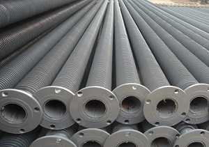
When that assembly is hot-dip galvanized, the finished part is fully immersed in molten zinc. A zinc–iron alloy layer forms on the base tube, the fin edges and the weld or wrap contact points. The result is a heating element that tolerates the constantly damp, fertiliser-rich atmosphere of a production greenhouse, where condensation, irrigation mist and occasional foliar spraying attack ordinary carbon steel quickly.
Lordfintube manufactures finned tubes for greenhouse heating circuits in carbon steel with aluminium or steel fins, with hot-dip galvanizing applied after finning. Related geometries are described on the spiral wound finned tubes page and the elliptical fin tube / oval fin tube page.
Core Definition: The Three Layers of the Product
A greenhouse heating finned tube is best understood as three functional layers working together.
- Base tube. Carries the heating medium and resists internal pressure. Nominal bore and wall thickness set the pressure rating and the water volume of the circuit.
- Fin layer. Bonded to the outside of the base tube by wrapping, welding or embedding. Fins raise the external surface area, which is the limiting side in any air-heated space.
- Hot-dip galvanized coating. A metallurgically bonded zinc layer that protects both the base tube and the fin roots against humid, slightly acidic greenhouse air.
The phrase "hot-dip galvanized" is not a paint or a wash. It means the whole finned tube was dipped into molten zinc, so the coating covers surfaces that cannot be reached by spraying, including the gap between adjacent fins and the underside of the fin wrap.
Parameters and Their Units
Four parameters drive almost every greenhouse heating design decision. Each is defined below with its unit.
Overall Heat Transfer Coefficient (U)
Unit: W/(m²·K). U expresses how much heat crosses one square metre of reference surface per kelvin of temperature difference. In finned tube work the reference surface is usually the total external surface (base tube plus fin surface), so the symbol is written Uo. Typical range for water-fed greenhouse finned tubes is roughly 20 to 60 W/(m²·K) when referred to the total external area, but the value depends on water velocity, fin density, fin efficiency and air velocity. Final selection must be confirmed against project specifications and manufacturer data.
Fin Efficiency (ηf)
Unit: dimensionless (0 to 1). A fin is never perfectly isothermal: its tip is cooler than its root. Fin efficiency is the ratio of actual heat transferred by the fin to the heat that would transfer if the whole fin sat at root temperature. Typical range for steel fins of moderate height is 0.80 to 0.95. Tall, thin fins in a low-conductivity material lose efficiency quickly.
Surface Expansion Ratio (Ao/Ai)
Unit: dimensionless. This ratio compares the total external surface area to the base tube surface area. Spiral finned tubes commonly achieve a ratio of 5:1 to 12:1, and denser geometries can go higher. A higher ratio increases heat output per metre of tube but also increases air-side pressure drop and the risk of dust or debris bridging between fins.
Heat Output per Unit Length (q′)
Unit: W/m. This is the practical number a greenhouse designer needs, because it converts directly into metres of pipe per bay. It depends on Uo, the surface area per metre, and the mean temperature difference between the heating water and the greenhouse air.
Formulas and Variables
Thermal output of a greenhouse heating finned tube is calculated from the basic heat exchanger relationship.
Where:
- Q = heat output, W
- Uo = overall heat transfer coefficient referred to the external surface, W/(m²·K)
- Ao = effective external surface area, m²
- ΔTlm = logarithmic mean temperature difference between the heating medium and the air, K
The logarithmic mean temperature difference is:
Where ΔT1 is the temperature difference at the inlet of the tube and ΔT2 is the temperature difference at the outlet, both in K. When the water temperature drop across a circuit is small, the arithmetic mean difference is often used as a simplification, but the logarithmic form is the more accurate one.
The effective external surface area accounts for fin efficiency:
Fin efficiency for a straight fin of uniform cross-section is:
Where:
- h = air-side convective heat transfer coefficient, W/(m²·K)
- k = thermal conductivity of the fin material, W/(m·K)
- t = fin thickness, m
- L = corrected fin height, m
- m = fin parameter, 1/m
Different standards and manufacturers use different reference areas for U. Some publish values based on the bare tube area, others on the total external area. Mixing the two produces errors of a factor of five or more. Always confirm which reference area a quoted U value uses before comparing products.
How the Core Parameters Interact
The four parameters are not independent. Increasing fin density raises Ao/Ai and therefore output per metre, but the narrower gap reduces air velocity between fins and can lower the effective h. Increasing fin height raises area but lowers fin efficiency. Increasing water velocity raises the inside film coefficient and therefore Uo, but it also raises pump power.
A hot-dip galvanized coating adds a thin zinc layer with lower thermal conductivity than steel. The effect on Uo is small in normal coating thicknesses, but it is not zero, and it should be acknowledged in tight designs rather than ignored.
Comparison: Bare Tube, Spiral Finned Tube and Oval Finned Tube
| Dimension | Bare Steel Tube | Spiral Wound Finned Tube | Elliptical / Oval Finned Tube |
|---|---|---|---|
| External surface per metre | Low (reference 1:1) | High, typically 5:1 to 12:1 | Moderate to high, geometry-dependent |
| Heat output per metre | Lowest | Highest for a given water temperature | Between the two |
| Air-side pressure drop | Lowest | Higher, rises with fin density | Lower than spiral at similar area |
| Resistance to dust and debris bridging | Best | Depends on fin pitch | Good, wider effective channels |
| Floor footprint in the crop zone | Large pipe length required | Compact | Compact |
| Cleaning effort | Easy | Requires wider pitch if cleaning is frequent | Moderate |
| Typical role in a greenhouse | Rail heating, frost protection loops | Main growing-pipe heating, high-output circuits | Layouts where airflow and space matter |
Technical Specifications
The table below describes common configurations. Values are typical ranges and must be confirmed against the project specification and the manufacturers data before ordering.
| Parameter | Typical Range | Unit | Notes |
|---|---|---|---|
| Base tube outside diameter | 16 – 38 | mm | Selected with pressure and flow requirement |
| Base tube wall thickness | 1.5 – 3.0 | mm | Governs internal pressure rating |
| Fin height | 8 – 16 | mm | Taller fins raise area but lower fin efficiency |
| Fin pitch | 2.5 – 6.0 | mm | Wider pitch suits dusty or cleaning-intensive houses |
| Fin thickness | 0.3 – 0.5 | mm | Affects fin efficiency and mechanical durability |
| Tube length | up to 6000 | mm | Limited by transport and handling |
| Zinc coating mass | typically 400 – 600 | g/m² | Project-specific; confirm against the applicable standard |
| Maximum working temperature (water) | up to 110 | °C | Confirm with pressure rating and circuit design |
Materials and Standards
Material selection for a greenhouse heating finned tube balances thermal performance, corrosion life and cost.
| Component | Common Material | Frequently Referenced Standard |
|---|---|---|
| Base tube | Carbon steel, seamless or welded | ASTM A106 / ASTM A179 (typical reference) |
| Fin | Aluminium 1050 / 1060, or carbon steel | Manufacturer specification |
| Galvanized coating | Zinc, hot-dip applied after finning | ASTM A123 / ISO 1461 (typical reference) |
| Documentation | Mill test certificate | EN 10204 3.1 (typical reference) |
The standards listed here are the ones most often requested for this product family. Where a project specifies a different standard, or a different coating mass, the project specification takes precedence. Confirm the exact standard and acceptance criteria in writing before production.
Hot-dip galvanizing is normally applied after the fins are attached. If the fins are aluminium, a steel fin construction is usually chosen instead, because aluminium cannot survive the molten zinc bath. This is one of the earliest decisions in any greenhouse project.
Application Industries
Hot-dip galvanized finned tubes serve a broad set of humid, warm and corrosive environments.
- Commercial greenhouses and nurseries. Growing pipes, rail heating, frost protection circuits and perimeter loops.
- Horticultural propagation. Bench and floor heating under misting and high-humidity conditions.
- Agricultural livestock buildings. Where ammonia and moisture accelerate corrosion.
- Industrial HVAC and air heating. Duct-mounted and free-standing unit heaters.
- Food and beverage processing spaces. Wash-down areas requiring corrosion-resistant heat exchangers.
Selection for Greenhouse Projects
Choosing the right tube for a greenhouse heating circuit follows a logical sequence.
- Establish the heat load. Calculate the peak transmission and ventilation loss of the house in kW, using the local design outdoor temperature.
- Set the water temperature regime. Lower flow temperatures require more surface area. A 60/50 °C regime needs substantially more tube than a 90/70 °C regime for the same heat output.
- Choose the fin geometry. Wide fin pitch where dust, leaf litter or cleaning is a concern. Denser pitch where maximum output per metre matters.
- Confirm the corrosion environment. Greenhouses with sulphur vaporisers, high fertiliser use or coastal exposure demand a heavier zinc coating.
- Check the pressure rating. Match base tube diameter and wall thickness to the circuits working pressure and the pump head available.
- Verify the layout. Tube length, spacing between runs and distance to the crop determine how evenly heat is distributed.
- Confirm the connection details. End connections, headers and supports must be compatible with the galvanized finish.
Design Trade-offs to Resolve Early
- Fin density versus fouling. Dense fins deliver more heat per metre but trap dust and organic debris. In a working greenhouse, a wider pitch is often the better long-term choice.
- Fin height versus efficiency. Taller fins add surface but progressively less useful surface, because tip temperature falls.
- Coating thickness versus heat transfer. A heavier zinc layer lasts longer but adds a small thermal resistance. The trade is normally worth taking in a greenhouse.
- Tube diameter versus pump power. Larger bore reduces water velocity and pump head but also reduces the inside film coefficient.
- Capital cost versus service life. Hot-dip galvanizing raises the initial cost and reduces the replacement frequency, which usually dominates over a multi-season horizon.
Quality Control and Inspection
Inspection of hot-dip galvanized finned tubes covers the coating, the geometry and the pressure boundary. Typical checks include:
- Visual examination of the coating for bare spots, runs, ash inclusions and roughness
- Coating thickness measurement by magnetic gauge at defined positions along the tube and on the fins
- Coating adhesion assessment, for example by a hammer test on a sample piece
- Dimensional inspection of base tube diameter, wall thickness, fin height, fin pitch and overall length
- Hydrostatic or pneumatic pressure test of the base tube
- Fin-to-tube bond check, since a loose fin acts as a thermal break
- Chemical composition and mechanical property verification of the base tube via mill certificate
- Salt spray testing where a project requires an accelerated corrosion benchmark
The exact test plan is agreed per order. Where a project specifies additional tests, they are added to the inspection plan rather than assumed.
Packing, Storage and Shipping
Finned tubes are easily damaged in transit if they are not restrained properly. Standard practice includes:
- Bundling with steel or plastic strapping at intervals along the length
- Protective end caps on tube ends and on threaded or flanged connections
- Wooden cradles, pallets or crates sized to the tube length
- Interleaving or edge protection to prevent fin-to-fin abrasion
- Moisture protection for sea freight, including desiccant where required
- Clear labelling of bundle weight, length and orientation
On site, store bundles on dry, ventilated ground with dunnage underneath. Avoid dragging bundles across concrete, and avoid stacking that puts point loads on the fin edges. Hot-dip galvanized surfaces develop a natural zinc patina over time; this is normal and does not indicate a coating defect. Wet storage staining, by contrast, is a handling issue that can be avoided by keeping bundles dry and separated.
Frequently Asked Questions
What is a greenhouse heating finned tube?
The finned construction allows a lower water temperature to deliver the same heat output as a bare pipe, which suits modern low-temperature greenhouse heating systems and heat pump or condensing boiler circuits.
Why is hot-dip galvanizing used for greenhouse finned tubes?
Hot-dip galvanizing forms a zinc–iron alloy layer that is metallurgically bonded to the steel. Unlike a spray coating, the molten zinc reaches the gaps between fins and the underside of the fin wrap, so the whole assembly is protected rather than just the visible outer surface.
How is the heat output of a finned tube calculated?
In formula form: Q = Uo × Ao × ΔTlm. The critical step is identifying which reference area the U value is based on, because values quoted on bare tube area and on total external area differ by a large factor.
How does fin pitch affect greenhouse heating performance?
In a clean, well-managed greenhouse, a denser fin pitch is often practical. In houses with high dust, leaf litter or frequent chemical application, a wider pitch reduces cleaning frequency and maintains performance over the season.
What water temperature is suitable for a greenhouse finned tube circuit?
Lower flow temperatures require more tube surface for the same heat output. The final regime should be set by the heating engineer together with the heat source characteristics and the required crop-zone temperature.
Does hot-dip galvanizing reduce heat transfer?
Zinc has lower thermal conductivity than steel, and a coating of normal thickness adds a measurable but small resistance to the heat path. In greenhouse service, where the alternative is progressive corrosion and eventual leakage, the trade is normally clearly in favour of galvanizing.
How should fin height be selected?
Fin efficiency falls as fin height rises and as fin thickness falls. Steel fins with a height in the range of 8 to 16 mm are common for greenhouse heating, but the correct value follows from the thermal calculation, not from a rule of thumb.
How do you match tube length to the greenhouse heat load?
If the greenhouse needs 120 kW and the selected tube delivers 400 W per metre at the design conditions, the circuit requires approximately 300 metres of tube. The figure must then be distributed across the house in a layout that keeps heat distribution even and respects access for crop work and maintenance.
Contact For Quotation
Send the greenhouse heat load, water temperature regime, required tube length and the corrosion environment. Lordfintube will confirm the base tube diameter, fin geometry, galvanizing specification and quantity for your project.
Request a Quote