

What are the components of a heat exchanger tube bundle?
Complete Heat Exchanger Tube Bundle Components
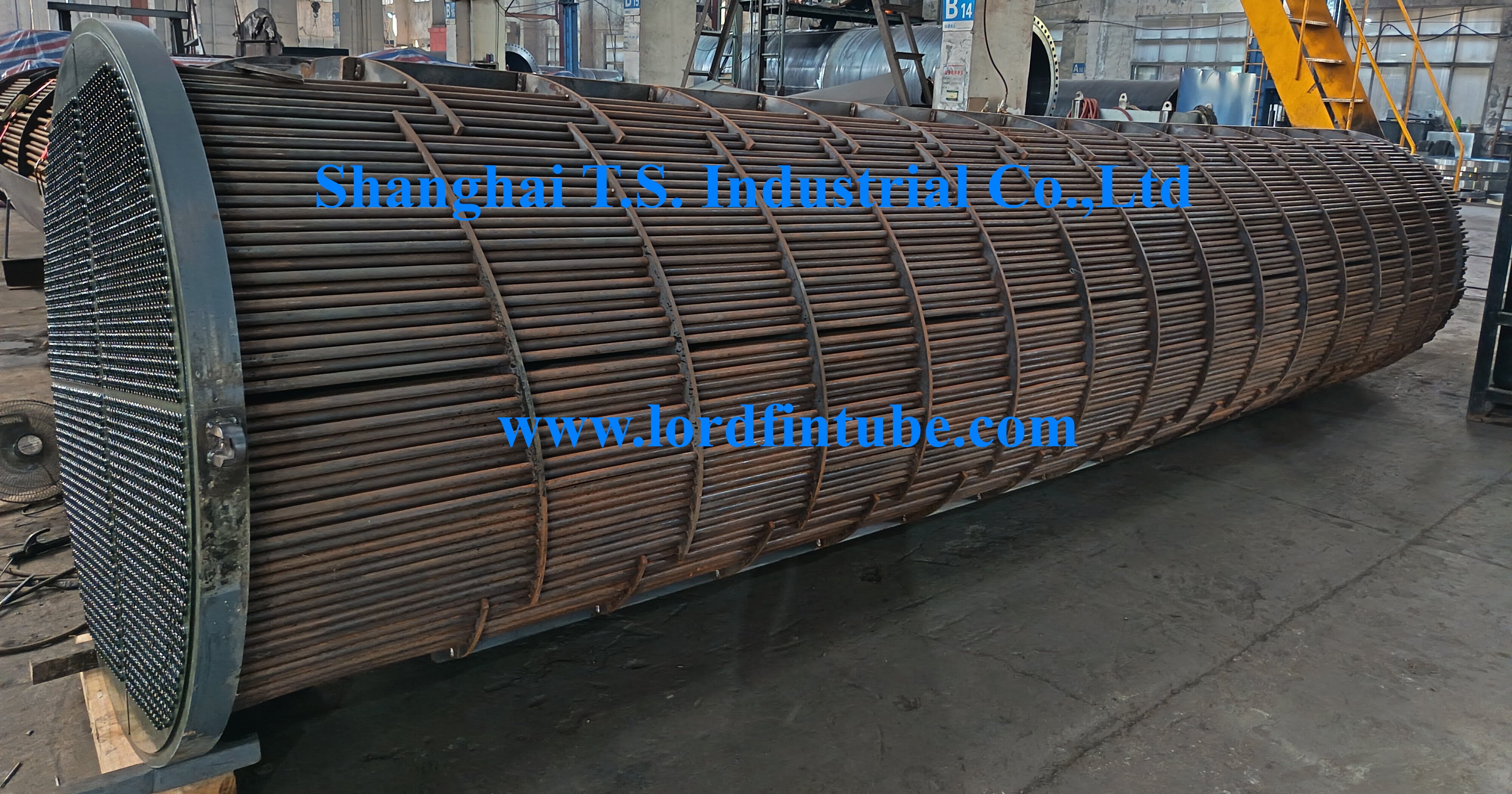
The tube bundle serves as the core heat transfer component in shell and tube heat exchangers. Its design quality, manufacturing precision, and assembly accuracy directly influence equipment efficiency, pressure drop characteristics, mechanical reliability, and operational lifespan.
A complete heat exchanger tube bundle comprises precision-assembled components including tube sheets, heat transfer tubes, baffle plates, tie rods, spacer tubes, nuts, and lifting eye bolts. This assembly mounts within the exchanger shell, performing the critical function of isolating tube-side and shell-side fluids while facilitating efficient thermal energy transfer between them.
Heat Exchanger Tube Bundle Types
U-Tube Bundle
Single tube sheet design with U-shaped tubes allowing thermal expansion accommodation
Straight Tube Bundle
Dual tube sheet configuration suitable for various applications with straightforward maintenance
Complete Tube Bundle Component
| Component | Location | Function |
|---|---|---|
| Heat Transfer Tubes | Primary bundle structure | Provide heat transfer surface area for thermal exchange between fluid media |
| Tube Sheet |
- Straight tube bundle: One at each end - U-tube bundle: Single end configuration |
- Secures all heat transfer tubes at both ends - Completely separates tube-side and shell-side fluids to prevent cross-contamination - Withstands differential pressure and thermal stresses between tube and shell sides |
| Baffle Plates | Central bundle section (multiple plates per bundle) |
- Support heat transfer tubes and prevent bundle vibration - Redirect shell-side fluid flow direction and velocity to promote cross-flow across tubes, enhancing heat transfer efficiency - Increase fluid turbulence to reduce fouling accumulation |
| Tie Rods + Nuts | Between baffle plates and tube sheet | Pass through all baffle plates and secure the complete baffle assembly to the tube sheet using end nuts, creating a stable integrated structure |
| Lug | Tube sheet periphery | Facilitates bundle installation, extraction, and provides internal shell support and positioning |
| Sealing Bar | Longitudinally installed on baffle plate edges, positioned adjacent to heat exchanger shell interior wall | Physically blocks annular bypass channel between bundle and shell, directing majority of fluid through baffle-prescribed paths across tube bundle |
| Spacer Tube | Sleeved over tie rods, positioned between baffle plates | Precisely maintains specified spacing between adjacent baffle plates |
| Eye Bolt | Mounted on tube sheet | Enables complete bundle installation, maintenance, and extraction; essential maintenance component |
Tube Sheet to Tube Connection Methods
The connection interface between tube sheets and heat transfer tubes represents the most critical and technically demanding manufacturing process. This joint must maintain pressure integrity under high-pressure conditions to prevent fluid mixing between shell-side and shell-side media, while providing adequate pull-out resistance to withstand operational pressures, thermal cycling, and various fluid-induced stresses.
| Connection Method | Principle | Advantages | Disadvantages | Application Scenarios |
|---|---|---|---|---|
| Strength Expansion | Utilizes mechanical or hydraulic expansion tools to plastically deform tube ends beyond tube sheet holes while maintaining elastic tube sheet condition, generating contact pressure for sealing and retention | Simple configuration, lower manufacturing expense, absence of thermal stress | Relatively limited pull-out strength, potential sealing degradation at elevated temperatures | Design pressure ≤4.0MPa, design temperature ≤300°C, applications without severe vibration or significant stress corrosion |
| Strength Welding | Direct fillet welding between tube ends and tube sheet holes creates robust metallic bonding | Exceptional sealing performance, very high pull-out strength, suitable for high-temperature, high-pressure and severe vibration conditions | Potential welding thermal stress and intergranular corrosion; tube sheet holes require grooving, increasing processing complexity; challenging repair if tube leakage occurs | Applications involving high temperatures, high pressures, hazardous media (flammable, explosive, toxic) and situations requiring maximum sealing integrity |
| Expansion + Welding | Combines expansion and welding in single joint. Two approaches: Strength expansion + seal weld (expansion carries load, weld provides sealing) or Strength weld + light expansion (weld carries load, light expansion eliminates gaps) | Combines advantages of both techniques, eliminates crevice corrosion, provides extremely high connection strength and sealing integrity, maximum reliability | Most complex manufacturing process, highest cost | Currently the most reliable and extensively applied high-performance connection method, particularly for demanding conditions involving high temperature/pressure, alternating loads, and stress corrosion susceptibility |
Baffle Plate Notch Function and Design
The baffle plate notch (particularly the segmental notch configuration) constitutes a fundamental design element determining shell-side fluid flow patterns and thermal transfer efficiency.
Primary Notch Functions
- Direct Fluid Flow for Optimal Pathways: Creates continuous transverse fluid channels forcing zigzag flow patterns across tube bundles, disrupting boundary layers along tube walls and significantly enhancing heat transfer.
- Regulate Velocity and Window Area: Notch dimensions (percentage of diameter) directly determine flow area in window zones, influencing fluid velocity and pressure drop characteristics.
- Support Tubes While Permitting Fluid Passage: Baffle plate bodies provide tube support while notch areas (without tubes) allow necessary space for fluid redirection and collection.
- Facilitate Drainage and Venting: During equipment filling or draining operations, the flow paths created by notches assist gas removal and liquid drainage, preventing air pockets or stagnant zones.
Notch Layout Strategies
- Horizontal Exchangers (shell-side single-phase clean liquid): Baffle notches should orient horizontally (vertical alignment).
- Gas-liquid mixtures or solids-containing fluids: Notches should orient vertically (horizontal alignment) with drain openings at baffle lowest points.
- Gases containing minimal liquid: Notches facing upward with drain openings at baffle lowest points.
- Liquids containing minimal gas: Notches facing downward with vent openings at baffle highest points.
Tube Bundle Manufacturing Process
Tube Sheet Machining
Deep hole drilling creates tube holes with precise groove specifications and surface finishes
Baffle Plate Fabrication
Precision control of tube hole dimensions and external diameters ensures proper clearance with shell interior walls
Bundle Tube Installation
Sequential passage of heat transfer tubes through tube sheets and baffle plates in controlled clean environments
Tube End Securement
Fixing heat transfer tubes according to selected connection methodology (expansion, welding, or combined approach)
Complete Assembly
Utilizing tie rods and spacer tubes to securely fasten baffle plates to tube sheets