


A finned tube only performs as well as the joint that holds the fin to the tube. When engineers compare a laser welded finned tube vs HFW finned tube, the decision usually comes down to bond quality, heat input, material compatibility, and cost per meter. This article breaks down how each process forms the fin-to-tube connection, which parameters control performance, and where each type fits best in real heat transfer equipment.
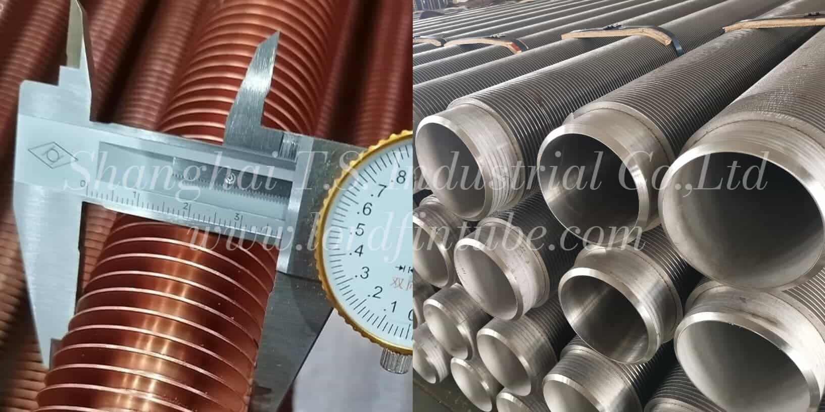
Laser Welded Finned Tube vs HFW Finned Tube: What Is the Actual Difference?
Laser welding uses a focused beam to melt a narrow zone at the fin root, producing a low heat input, high precision joint. High frequency welding (HFW) uses high frequency current and mechanical pressure to forge the fin edge onto the tube, producing a wider bonded zone at higher heat input and higher production speed.
The short answer: laser welding gives tighter geometry control and lower thermal distortion, while HFW gives a broader, deeper bond at lower cost per meter on thick fins and large tube diameters. Neither is universally better — the correct choice depends on the specification.
What Is a Laser Welded Finned Tube?
A laser welded finned tube is a welded finned tube in which a continuous, focused laser beam melts the fin root and a thin layer of the tube surface simultaneously. The molten pool solidifies quickly, creating a metallurgical bond with a narrow heat affected zone (HAZ).
Typical characteristics of laser welded construction:
- Narrow weld bead with low thermal distortion of the base tube
- Low heat input per unit length, which limits grain growth in the HAZ
- Suitable for thin fins and small diameter tubes where HFW equipment cannot reach
- Good for stainless steel, alloy steel, copper alloys, and some nickel alloys
- Cleaner surface finish with minimal weld spatter
What Is a High Frequency Welded (HFW) Finned Tube?
A high frequency welded finned tube is produced by passing high frequency alternating current (typical range 200–500 kHz, final value to be confirmed by the manufacturer) through the fin edge while the fin is pressed against the tube. Contact resistance at the fin-to-tube interface generates intense local heating, and the pressure forges the two surfaces together.
Typical characteristics of HFW construction:
- Wide, deep bonded zone with high mechanical strength
- Higher heat input than laser welding, with a wider HAZ
- Very high production speed, which lowers cost per meter on large runs
- Best suited to carbon steel, low alloy steel, and thicker fin stock
- Well established in air-cooled heat exchangers, economizers, and boiler applications
How Each Process Bonds the Fin to the Tube
Laser welding sequence
- The fin is positioned and held against the tube by a mechanical or rolling fixture.
- A laser head focuses the beam at the fin root; the beam may be stationary with a rotating tube, or traverse along the tube axis.
- The fin root and a shallow tube layer melt and mix.
- The pool solidifies within milliseconds, forming a narrow metallurgical bond.
High frequency welding sequence
- The fin strip is fed continuously and wrapped around the tube.
- Electrodes apply high frequency current near the fin root.
- Interface resistance and skin effect heat the fin edge and tube surface to forging temperature.
- Roller pressure forges the heated surfaces together, extruding oxides and forming a solid-state bond.
Core Parameters and Units
Four parameters separate these two processes in daily engineering practice. All values below are typical range only — final values must follow the project specification, engineer confirmation, and manufacturer data.
1. Weld heat input
Heat input is the energy delivered per unit length of weld, expressed in joules per millimeter (J/mm) or kilojoules per millimeter (kJ/mm). It controls penetration depth, HAZ width, and the risk of fin burn-through.
2. Bond ratio / penetration
Bond ratio is the percentage of the available fin-root contact length that is metallurgically joined, expressed in percent (%). Penetration depth is reported in millimeters (mm). A higher bond ratio reduces contact resistance and improves mechanical retention.
3. Fin-to-tube contact resistance
Contact resistance is the thermal resistance across the fin-to-tube interface, expressed in square meter kelvin per watt (m²·K/W) or, for a unit tube length, in kelvin meter per watt (K·m/W). It is the single largest driver of finned tube thermal performance after fin geometry.
4. Welding speed
Welding speed is the rate at which the joint is completed, expressed in meters per minute (m/min) or millimeters per second (mm/s). It trades directly against heat input for a fixed power source.
How the parameters interact
These parameters are not independent. For a fixed power source, increasing welding speed lowers heat input, which reduces penetration and bond ratio. Raising power restores penetration but widens the HAZ. Higher heat input also increases the risk of fin tip melting and tube ovality on thin wall tubes. Contact resistance falls as bond ratio rises, but only up to the point where additional heat begins to degrade the base material.
How Is Weld Heat Input Calculated?
Heat input applies to any fusion welding process, including laser welding. The general expression is:
- H = heat input, joules per millimeter (J/mm)
- P = effective power delivered to the workpiece, watts (W), where 1 W = 1 J/s
- v = welding speed, millimeters per second (mm/s)
Worked example (illustrative only, not a project value): if effective laser power is 1,200 W and travel speed is 50 mm/s, then H = 1,200 ÷ 50 = 24 J/mm. Reducing speed to 25 mm/s at the same power doubles heat input to 48 J/mm, which typically deepens penetration and widens the HAZ.
For high frequency welding, the heat generated at the interface follows Joule heating:
- Q = heat generated, joules (J)
- I = RMS current through the fin-to-tube interface, amperes (A)
- R = interface contact resistance during heating, ohms (Ω)
- t = heating time, seconds (s)
Heat input per unit length is then Q divided by the travel distance over the same period. Because R changes as the interface heats and forges, HFW heat input is normally set empirically on the machine rather than predicted from a single formula.
Contact resistance and fin efficiency
- R_c = fin-to-tube contact resistance, m²·K/W
- ΔT = temperature drop across the interface, kelvin (K)
- q = heat flux through the interface, watts per square meter (W/m²)
A poor bond raises R_c, lowers the effective fin efficiency, and forces a larger surface area or a longer tube bundle to reach the same duty.
Laser Welded vs HFW Finned Tube: Comparison Table
| Comparison dimension | Laser welded finned tube | HFW finned tube |
|---|---|---|
| Bonding mechanism | Fusion welding of fin root and tube surface | Solid-state forging under high frequency resistance heating |
| Heat input | Low, typically a few J/mm to tens of J/mm | Higher, with a wider heated zone |
| Heat affected zone | Narrow; limited base material degradation | Wider; requires attention on heat-sensitive alloys |
| Bond ratio | High on the welded root line | High over a broader contact band |
| Fin thickness capability | Thin fin stock, typical range 0.2–1.2 mm | Thicker fin stock, typical range 0.8–3 mm |
| Tube diameter range | Small to medium, typical range 8–51 mm OD | Medium to large, typical range 16–219 mm OD |
| Material range | Carbon steel, stainless steel, alloy steel, copper alloys, nickel alloys | Mainly carbon steel and low alloy steel; stainless grades with process control |
| Production speed | Moderate; depends on beam path and fixturing | High; continuous strip feed and wrap |
| Distortion and ovality | Low, suitable for thin wall tubes | Higher; pressure rolls and heat can affect roundness |
| Surface finish | Clean, minimal spatter | Visible bond line, sometimes with flash |
| Relative cost structure | Higher equipment cost, lower consumable waste | Lower cost per meter on long production runs |
| Typical use | Compact heat exchangers, precision coils, thin fin designs | Air-cooled heat exchangers, economizers, boiler and process heaters |
Design Trade-offs: Bond Quality, Cost, and Material Compatibility
Every finned tube specification is a balance. The main trade-offs are below.
- Heat input vs penetration. More heat means deeper penetration and a higher bond ratio, but also a wider HAZ, more distortion, and a greater risk of burning thin fins.
- Speed vs bond quality. Pushing welding speed raises output and lowers cost, but reduces the time available for melting or forging, which can leave unfused segments along the fin root.
- Fin thickness vs thermal performance. Thicker fins conduct heat better at the root but add weight, cost, and fin-side pressure drop for the same pitch.
- Capital cost vs running cost. Laser systems carry a higher initial investment; HFW systems are cheaper per meter at high volume but less flexible on small diameters and thin stock.
- Material compatibility. High carbon equivalent steels and some stainless grades respond differently to rapid heating and forging; the welding method must match the metallurgy, not the other way around.
Technical Parameter Table
| Parameter | Unit | Typical range |
|---|---|---|
| Base tube outside diameter | mm | 8–219 |
| Base tube wall thickness | mm | 0.8–12 |
| Fin height | mm | 3–32 |
| Fin thickness | mm | 0.2–3.0 |
| Fin pitch (fins per inch equivalent) | mm | 2–12 |
| Tube length | mm | Up to 12,000 depending on handling and transport limits |
| Weld heat input (laser) | J/mm | 5–50 |
| Bond ratio | % | To be confirmed by destructive or metallographic test |
| Fin-to-tube contact resistance | m²·K/W | To be confirmed by thermal test or supplier data |
Materials and Standards
Finned tubes are produced in carbon steel, low alloy steel, stainless steel, and selected non-ferrous alloys. Common base tube grades include carbon steel and low alloy boiler and heat exchanger grades, austenitic stainless steels, and copper or copper-nickel alloys for specific duties. Fin material is usually matched to the base tube to limit galvanic and expansion mismatch.
Standards and acceptance criteria are set by the project specification. Where no standard is nominated, the applicable standard to be confirmed should be agreed in writing before production, covering tube dimensions, weld quality, bond ratio, and surface condition. Typical documentation requested on finned tube orders includes material certificates, dimensional inspection records, and bond or weld test reports according to the project specification.
Application Industries
- Air-cooled heat exchangers and condensers in oil, gas, and petrochemical plants
- Economizers, air preheaters, and waste heat recovery units in power generation
- Boiler convection and superheater sections
- Process gas coolers and heaters in chemical and fertilizer plants
- Refrigeration and HVAC coils where compact geometry matters
- Marine and offshore heat transfer equipment requiring corrosion resistance
Selection Guide: Laser Welded or HFW?
Use the following logic as a starting point, then confirm with the project engineer.
Choose laser welded finned tube when:
- Fin thickness is below roughly 1 mm and burn-through is a concern
- Tube outside diameter is small and HFW electrodes cannot be positioned reliably
- The base material is stainless steel, an alloy grade, or a non-ferrous alloy sensitive to a wide HAZ
- Dimensional tolerance and surface cleanliness are critical
- Production volume is moderate and changeover flexibility matters
Choose HFW finned tube when:
- Tube diameters are large and fin stock is thick
- Carbon steel or low alloy steel is the specified material
- High volume and low cost per meter drive the project
- A broad, forged bond is preferred for mechanical robustness
- The application is a conventional air-cooled or boiler duty with established HFW practice
Quality Control and Inspection
Inspection scope follows the purchase specification. Typical checks on welded finned tube include:
- Base tube dimensional and wall thickness verification
- Fin height, fin thickness, and fin pitch measurement
- Visual examination of the weld or bond line for discontinuities
- Bond ratio assessment by peel, twist, or metallographic section
- Weld penetration measurement on samples
- Hydrostatic or pneumatic leak testing of the base tube where specified
- Surface condition and corrosion protection checks
- Straightness and ovality measurement
Test frequency, sampling plan, and acceptance limits are set by the project specification and confirmed by the manufacturer before the order is released.
Packing and Shipping
Finned tube is easily damaged in transit because the fins are thin and closely spaced. Standard protection measures, to be confirmed against the project requirement, include:
- End caps or plastic plugs on tube ends to protect bores and threads
- Fin protection strips or sleeves at sling and support points
- Bundling with steel or plastic strapping and timber separators
- Wooden crates or steel frames for long or thin wall tubes
- Moisture barrier and desiccant for sea freight
- Clear handling marks and lifting point identification
Bundle weight and length limits should be agreed with the freight forwarder, especially for tube lengths above roughly 12 m.
FAQ
What is the main difference between a laser welded finned tube and an HFW finned tube?
Laser welding melts a narrow zone at the fin root with low heat input, producing a precise joint with a small heat affected zone. HFW uses high frequency current plus mechanical pressure to forge a wider bond, giving higher production speed and a broader bonded area at higher heat input.
Which process gives a stronger fin-to-tube bond, laser or HFW?
It depends on the specification rather than the process name. HFW generally produces a wider forged bond on thick fins and large tubes, while laser welding produces a concentrated, high-integrity fusion bond on thin fins and small diameters. Bond strength must be verified by test according to the project specification.
Can HFW finned tube be used at high service temperature?
HFW finned tube is widely used in boiler and process heater duties. The allowable service temperature depends on the base tube and fin material, the bond quality, and the thermal cycling profile, and must be confirmed for each project rather than assumed.
Is laser welded finned tube better for thin fins and small tube diameters?
Yes, in most cases. The focused beam and low heat input reduce the risk of burning through thin fin stock, and the small weld zone limits distortion of small diameter tubes. Exact limits should be confirmed with the manufacturer for the specific geometry.
How is weld heat input calculated for laser welded finned tube?
Heat input is H = P / v, where H is in joules per millimeter, P is the effective power in watts, and v is the welding speed in millimeters per second. Raising speed at constant power reduces heat input and therefore penetration.
How does contact resistance affect finned tube performance?
Contact resistance is the thermal resistance across the fin-to-tube interface. A poor bond raises this value, lowers effective fin efficiency, and requires more surface area to achieve the same heat duty. It is calculated as R_c = ΔT / q, with ΔT in kelvin and q in watts per square meter.
Which option is more economical?
HFW usually delivers a lower cost per meter on high volume runs in carbon and low alloy steel. Laser welding is often more economical where thin fins, small diameters, stainless or alloy materials, and tight tolerances make HFW impractical. A total cost comparison should include scrap rate, inspection effort, and service life.
What should be specified when requesting a quote for welded finned tube?
Provide base tube material and dimensions, fin material, fin height, fin thickness, fin pitch, tube length, welding method preference, operating temperature and pressure, corrosion environment, inspection requirements, and the applicable standard. This allows the manufacturer to confirm feasibility and tolerances before pricing.
Need help selecting between laser welded and HFW finned tube for your heat transfer duty? Send your tube dimensions, materials, and operating conditions and our engineering team will review the specification.