


Longitudinal Finned Tubes in Waste Heat Recovery: What Works in Dirty Flue Gas?
Industrial flue gases commonly waste 15‑40% of total fuel energy. Waste‑heat recovery cuts operating costs and lowers carbon emissions, yet many real‑world projects underperform.
Fouling from ash, dust and sticky particulate deposits is the main culprit. Many plants select standard transverse finned tubes only to see heat‑transfer efficiency drop sharply within weeks. This article reviews when longitudinal finned tubes deliver reliable service for dusty flue‑gas conditions.
How Longitudinal Finned Tubes Perform in Dirty Flue Gas
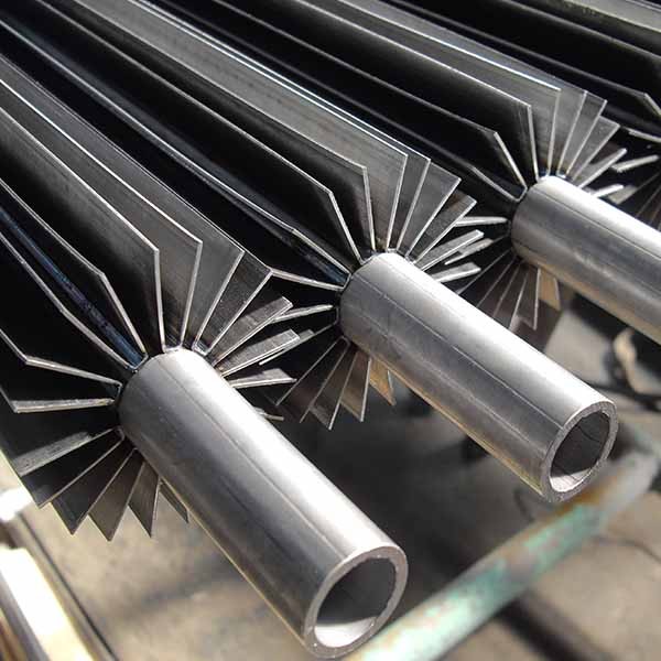
With transverse fins, gas weaves between disc‑shaped fins, creating turbulence that boosts clean heat transfer – but also traps ash in stagnant zones. Longitudinal fins, by contrast, run parallel to the tube axis. The gas path is straight, with no sudden expansions. Particles stay entrained, and the smooth fin surfaces shed deposits more readily. The result: sustained thermal performance without frequent sootblowing.
There is a trade‑off, though. Longitudinal fins generally yield a lower heat‑transfer coefficient per unit area than transverse fins. Yet the lower pressure drop often permits higher gas velocities, which can partially compensate. And in practice, the average performance over months of operation frequently beats a transverse unit that has become partially fouled.
Key insight: Longitudinal finned exchangers form the core of many medium‑ to low‑temperature waste‑heat recovery systems, especially where fouling is a concern. Older designs suffered from moderate efficiency, but under ideal test conditions, newer louvered or serrated longitudinal fins can boost heat‑exchange performance by up to 90 % compared with plain flat fins – without sacrificing the self‑cleaning geometry.
Longitudinal vs Transverse (Circular) Finned Tube: Real‑World Performance Trade‑offs
The table below compares typical behaviour for flue gas at 150–350 °C with moderate dust loading. Keep in mind that actual numbers vary with gas composition, particle size, and material selection.
| Parameter | Longitudinal Finned Tube | Transverse (Circular) Finned Tube | What This Means for Your Plant |
|---|---|---|---|
| Gas‑side pressure drop | Low (typically 200–600 Pa per row) | High (800–2000 Pa or more) | Longitudinal saves fan power and may allow retrofits without fan upgrades. |
| Fouling tendency (dusty gases) | Low – self‑cleaning geometry | High – particles wedge between fins | Longitudinal units maintain efficiency for months; cleaning intervals are longer. |
| Ease of mechanical cleaning | Straight lanes allow brushing or air lancing | Restricted access to fin gaps | Longitudinal can be cleaned online with rapping devices. |
| Heat transfer coefficient (clean basis) | Moderate (30–50 W/m²·K typical) | Higher (50–80 W/m²·K) | Transverse gives better clean performance, but degrades faster with fouling. |
| Fabrication cost (per unit area) | Generally lower for welded longitudinal fins | Higher due to complex geometry | Longitudinal often has lower initial capital cost. |
| Effectiveness in high‑velocity gas | Good – low drag allows velocities up to 15 m/s | Limited by erosion and pressure drop | Longitudinal can be downsized for the same duty, but erosion risk must be checked. |
| Compactness / Footprint | Lower – requires larger bundle volume for same clean‑gas duty | Higher – more compact for clean service | For clean gas, transverse fins give smaller footprint; longitudinal excels in dirty gas despite larger size. |
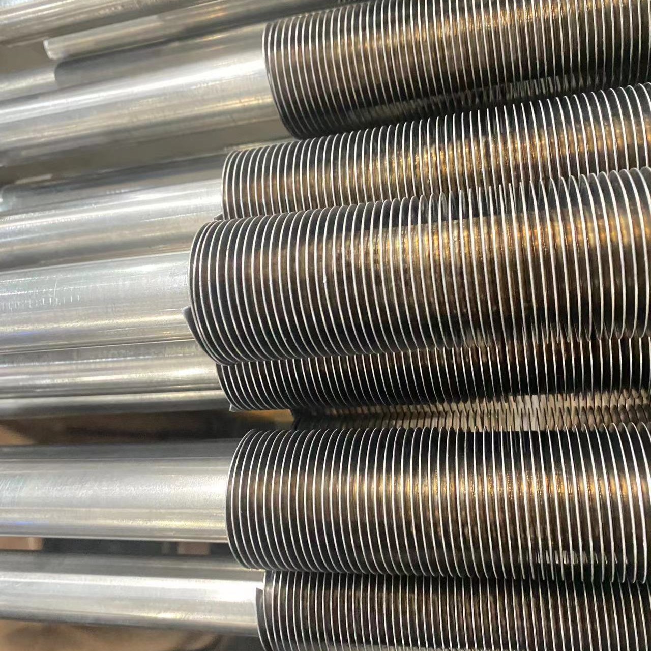
Which design wins? It depends on your flue gas composition. For clean gas (e.g., natural gas exhaust), transverse fins may be more compact. But for the majority of industrial applications – cement, steel, glass, ceramics, biomass, and waste‑to‑energy – longitudinal fins are increasingly the preferred choice because they keep working when others choke.
Field Case Studies: Waste‑Heat Recovery Across Heavy Industries
Real‑site experiences show consistent patterns. The table below summarises typical applications and observed benefits, based on published field data from multiple installations.
| Industry / Application | Flue Gas Temperature Range | Waste‑heat recovery use | Reported Benefits |
|---|---|---|---|
| Aluminium electrolysis (pot gas) | 100 – 160 °C | Heating process water / space heating | Proven recovery on 400 kA lines; significant steam‑saving potential depending on site conditions. |
| Ceramic tunnel kilns | 250 – 400 °C | Preheating combustion air | Overall thermal efficiency improved by 8‑12%; cleaning intervals extended from weeks to >6 months in multiple plants. |
| Petrochemical reformer flue gas | 180 – 300 °C | Air preheating for burners | Fuel consumption reduced by 5‑7%; exchanger operated for 2 years between manual cleanings in one reported case. |
| Biomass boiler (wood dust) | 140 – 200 °C | District heating water | Maintained >85% of clean heat transfer after 1 year; transverse units in same service fell to ~60%. |
These results come from full‑scale industrial bundles, with tube lengths reaching 12 m. Real‑world installations consistently show improved uptime, higher annual heat recovery output and lower maintenance labour requirements.
Common Longitudinal Fin Profiles
- I Type: Flat fin strip welded edge‑on. Economical default for general service.
- T Type: Flanged fin foot for wider weld footprint and stiffer root – used for taller fins or higher temperatures.
- V Type: Folded V‑shape welded along two lines; self‑supporting with more surface per fin, resists vibration.
Typical Specifications
- Base Tube OD: 19 – 114 mm
- Fin Height: 12 – 25 mm (taller on T and V profiles)
- Fin Count: 8 – 36 around the circumference
- Materials: Carbon steel, alloy steel, stainless steel
Key Design Parameters for Specifying Longitudinal Finned Tube Bundles
Selecting the right geometry and material is critical. Beyond the basics, avoid these common mistakes:
Common Mistakes During Specification
- Too‑narrow fin spacing for high‑dust flue gas – this defeats the self‑cleaning benefit. For heavily dust‑laden gas, spacings of 8–12 mm are widely adopted; heavier ash loading may require above 10 mm.
- Over‑pursuing high gas velocity without evaluating particle erosion risk. Velocities of 8–14 m/s are common, but if particles are hard (e.g., silica), stay below 12 m/s or use erosion‑resistant materials.
- Ignoring material compatibility with corrosive components (chlorides, sulphur). Stainless steel or corten may be necessary, but they increase cost and affect weldability.
One frequent question: “Can I replace an existing transverse fin unit with longitudinal fins?” Often yes, because the lower pressure drop allows you to increase tube count or gas flow without changing the fan, potentially unlocking extra recovery capacity. But check your available space – longitudinal bundles are typically larger for the same clean‑gas duty.
Practical Maintenance & Cleaning for Longitudinal Finned Tube Heat Exchangers
The straight, continuous channels between fins make cleaning straightforward:
- Manual brushing with a long‑handled wire brush from both ends – no disassembly needed.
- Online cleaning via rapping mechanisms or acoustic horns – vibration travels along the fin length, dislodging deposits.
- High‑pressure air lances can traverse the full tube length.
- Water washing drains completely, avoiding corrosive puddles.
Many operators report cleaning frequencies one‑quarter of those for transverse units in the same service – fewer shutdowns and lower labour costs.
One practical constraint: laser‑welded longitudinal fins, while delivering extremely low thermal contact resistance, require careful control of wall thickness and base material compatibility. Thin walls (<2 mm) may distort during welding, and certain stainless grades are more prone to hot cracking. Always consult your fabricator about these limits.
Latest Advances in Longitudinal Finned Tube Manufacturing
Laser welding has largely replaced older mechanical bonding methods, eliminating thermal contact resistance. The weld is narrow and deep, creating a near‑monolithic joint that withstands thermal cycling. Some suppliers now offer louvred or serrated fins that introduce controlled turbulence – improving the heat‑transfer coefficient by 30‑50% while keeping pressure drop modest.
For condensing applications (flue gas with water vapour), vertical orientation promotes condensate drainage, reducing acid corrosion. Field trials indicate that stainless‑steel longitudinal finned coils can achieve long service life under condensing conditions, subject to proper material grade selection – but avoid expecting a specific hour number, as real life depends on gas composition and operating cycles.
Digital monitoring (infrared thermography, differential pressure tracking) is increasingly used to schedule cleaning based on actual fouling trends rather than fixed calendars – a data‑driven approach that balances recovery and maintenance.
When Should You Choose Longitudinal Finned Tubes for Waste‑Heat Recovery?
No two waste‑heat streams behave exactly alike. Longitudinal finned tubes make a robust solution for flue gas loaded with particulates, sticky tars or corrosive components – they will sustain performance where transverse fins would foul quickly. On the other hand, if your gas is clean (e.g., natural gas exhaust), transverse fins may give you a more compact, cost‑effective solution.
Even so, they are not suitable for every project. The larger bundle size for clean‑gas duty, the higher material cost for corrosion resistance, and the lower clean coefficient are real drawbacks. Evaluate your specific gas composition, space constraints, and cleaning strategy before deciding.
Frequently Asked Questions
For clean flue gas (low dust, no condensable tars), transverse fins are usually more compact and provide higher heat transfer per volume. Also, if space is extremely limited, longitudinal bundles may not fit.
Yes, in many cases. The lower pressure drop of longitudinal fins often allows higher gas flow or more tubes without upgrading the fan. However, check your available footprint – longitudinal bundles are typically larger.
Biomass flue gas often contains fine ash and sticky tars. A spacing of 10–12 mm is commonly recommended; wider spacing (≥10 mm) reduces bridging and makes cleaning easier.
Laser welding provides a narrower, deeper weld with extremely low contact resistance, improving heat transfer. However, it requires precise control of wall thickness and material composition; high‑frequency welding is more forgiving and economical for carbon steel in non‑critical services.
Service life heavily depends on flue‑gas corrosion, ash abrasion and operating temperature. With proper material selection, many field units run multiple years without major degradation.