

A membrane boiler economizer is a boiler pressure part that recovers heat from flue gas before the gas leaves the unit and transfers that heat to boiler feedwater. Because it joins parallel bare tubes with a continuous welded steel strip, it is also described as a diaphragm economizer or a membrane wall economizer.
What is a membrane boiler economizer?
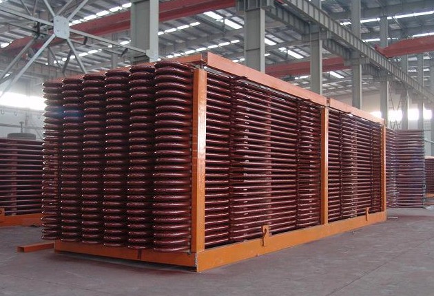
A membrane boiler economizer is an economizer whose tube bank is built as a welded tube-and-membrane wall instead of a set of free-standing bare tubes. A continuous flat steel diaphragm is welded longitudinally between two straight sections of smooth tube. The tubes and the diaphragms together form narrow longitudinal passages that guide the flue gas across the heating surface.
The main structural features are:
- A continuous flat steel strip welded between two straight tube sections along the full tube length.
- A diaphragm thickness typically in the range of 2 to 3 mm; the final value must be confirmed by project specification, engineer, and manufacturer data.
- Tubes connected to inlet and outlet headers at the ends of the bank.
- Tube rows usually arranged in several groups along the flue gas path.
Because the tubes and diaphragms are welded together, the bank acts as both a heat transfer surface and a flue gas guide. That dual function is the essential difference between a membrane economizer and a bare tube or a finned tube economizer.
How does a membrane boiler economizer work?
A membrane boiler economizer works by forcing flue gas through narrow passages formed by tubes and diaphragms while feedwater flows inside the tubes, so heat moves from the gas through the tube wall and the diaphragm into the water. The process follows a simple heat recovery path:
- Flue gas passes on the outside of the tube bank, normally in a direction close to counterflow to the water.
- Feedwater passes inside the tubes, entering at the cold end and leaving at the hot end.
- Heat crosses the tube wall and the diaphragm into the feedwater.
- Flue gas temperature falls, feedwater temperature rises, and stack loss is reduced.
The diaphragm contributes to heat transfer because it extends the gas-side surface and conducts heat along its width to the tube. It also stabilises the gas-side velocity field. In an open bare tube bank, gas can accelerate through local gaps; in a membrane bank, the narrow passages limit those local velocity peaks, which helps reduce localised wear on the tubes.
Heat balance and surface area equations
For a first-pass thermal check, the heat recovered by the economizer equals the heat absorbed by the water:
- Q — heat transfer rate, kW
- ṁg — flue gas mass flow, kg/s
- cp,g — flue gas specific heat, kJ/(kg·K)
- Tg,in, Tg,out — flue gas inlet and outlet temperature, °C
- ṁw — feedwater mass flow, kg/s
- cp,w — feedwater specific heat, kJ/(kg·K)
- Tw,in, Tw,out — feedwater inlet and outlet temperature, °C
The required heating surface follows from the overall heat transfer equation:
- A — heat transfer area, m²
- Q — heat transfer rate, W
- U — overall heat transfer coefficient referred to the gas-side area, W/(m²·K)
- ΔTlm — log mean temperature difference, K
ΔT1 and ΔT2 are the terminal temperature differences at the two ends of the surface, in K. A design that approaches true counterflow produces a higher log mean temperature difference and therefore needs less surface; the tube bank layout and the diaphragm passages influence how closely counterflow is approached. Calculation practices for U and ΔTlm differ between standards and manufacturers, so one method must be used consistently. Final values must be confirmed by project specification, engineer, and manufacturer data.
Which parameters govern membrane boiler economizer performance?
The performance of a membrane boiler economizer is governed mainly by heat transfer area, flue gas temperature drop, and feedwater temperature rise, supported by gas-side pressure drop, tube geometry, and design pressure and temperature. The table below summarises the key parameters, their units, and their influence.
| Parameter | Unit | What it describes | Effect on performance |
|---|---|---|---|
| Heat transfer area | m² | Gas-side surface exposed to the flue gas, including tube and diaphragm area | More area recovers more heat but raises pressure drop, weight, footprint, and cost |
| Flue gas temperature drop | °C | Reduction of flue gas temperature across the economizer | Directly reflects gas-side heat recovery and boiler efficiency |
| Feedwater temperature rise | °C | Increase of feedwater temperature across the economizer | Reflects water-side heat gain; limited by flow, pressure, and saturation margin |
| Gas-side pressure drop | Pa or kPa | Resistance of the tube bank to flue gas flow | Drives induced draft fan power and affects unit output |
| Tube pitch | mm | Centre-to-centre distance between adjacent tubes | Sets gas passage width and heating surface density |
| Diaphragm thickness | mm | Thickness of the flat steel membrane between tubes | Affects diaphragm heat conduction, stiffness, and weld quality |
| Design pressure | MPa | Water-side design pressure of the economizer | Sets wall thickness and material selection |
| Design temperature | °C | Design metal temperature for water and gas sides | Sets material grade and allowable stress |
| Material grade | — | Steel used for tubes and diaphragms | Affects corrosion allowance, wear resistance, and cost |
Heat transfer area (m²)
Heat transfer area is the single most influential parameter in the thermal design. At a given overall heat transfer coefficient and log mean temperature difference, a larger area raises the recovered heat Q, which appears as a larger flue gas temperature drop and a larger feedwater temperature rise. The cost of that gain is a higher gas-side pressure drop, greater weight, a larger footprint, and more material. In practice, area is not chosen for maximum heat recovery; it is chosen so that the target stack temperature is reached at an acceptable fan power, weight, and cost.
Flue gas temperature drop (°C)
Flue gas temperature drop expresses how much heat the gas side gives up between the inlet and outlet of the economizer. It is sensitive to heat transfer area, gas mass flow, inlet gas temperature, fouling on the gas side, and flow distribution between tube rows. It should be calculated backwards from the target stack temperature rather than taken from a fixed table. Actual achievable values must be confirmed by project specification, engineer, and manufacturer data.
Feedwater temperature rise (°C)
Feedwater temperature rise expresses the water-side heat gain. It depends on feedwater flow, inlet temperature, and pressure. The outlet temperature must remain below saturation at the working pressure with a suitable margin; otherwise steaming can occur inside the economizer, which is a recognised operating risk for economizers in general. The saturation margin is a project-specific decision and must be confirmed by the engineer and the manufacturer.
Gas-side pressure drop
Gas-side pressure drop rises roughly with the square of gas velocity. Narrow diaphragm passages and higher gas velocity both improve the heat transfer coefficient and increase pressure drop, so the fan duty and the boiler draught balance set a practical ceiling on how far the surface can be pushed. Fouling also raises pressure drop over time, so the design should leave a fouling allowance agreed with the project specification.
Tube pitch, diaphragm thickness, and passage geometry
Tube pitch and diaphragm thickness together determine the passage width, the heating surface density, the structural stiffness of the bank, and the fouling tendency. A narrower passage improves surface density and velocity uniformity but increases the risk of ash bridging and pressure drop. A thicker diaphragm adds stiffness and conduction area but increases weight and welding heat input.
Membrane, bare tube, and finned tube economizers compared
A membrane boiler economizer is usually compared with the bare tube economizer and the finned tube economizer when an economizer is selected for a boiler tail.
| Comparison dimension | Membrane economizer | Bare tube economizer | Finned tube economizer |
|---|---|---|---|
| Heating surface density | Moderate to high; tube plus diaphragm forms the surface | Low | High |
| Flue gas passage | Narrow longitudinal passages bounded by tubes and diaphragms | Open tube bundle | Open bundle with fins |
| Velocity field uniformity | Good; passages limit local velocity peaks | Variable | Variable |
| Wear behaviour | Generally favourable, helped by the even velocity profile | Moderate | Depends on fin design and gas velocity |
| Fouling and cleaning | Usually easier to clean than finned designs | Easy | More difficult; fins can bridge with ash |
| Metal content per unit surface | Generally lower than a comparable bare tube bank | Higher | Moderate |
| Manufacturing complexity | Higher; continuous diaphragm welding is required | Lower | Moderate |
| Structural stiffness of the bank | High rigidity, with limited elastic compensation | Flexible | Moderate |
| Typical application context | Boiler tails with moderate to high wear and ash load | Clean gas, smaller capacity | Clean gas, space-constrained layouts |
Design trade-offs in membrane economizer selection
Selecting a membrane boiler economizer is a balancing exercise. Five trade-offs dominate the design discussion.
Heat transfer versus pressure drop
Higher gas velocity and narrower passages increase the heat transfer coefficient and reduce the surface required, but gas-side pressure drop rises roughly with velocity squared. The balance is set by the induced draft fan capability and the acceptable stack temperature.
Fouling tendency versus tube spacing
Wider tube spacing and wider passages reduce the risk of ash bridging and make cleaning easier, but they lower heating surface density and therefore raise the physical size of the bank. Fuels with high ash content usually push the design toward wider spacing.
Cost versus corrosion allowance
Thicker tube walls and higher alloy content raise the corrosion and wear allowance and extend service life, but they also raise the material cost and the weight. The correct allowance depends on feedwater quality, flue gas composition, and the expected operating regime.
Weight versus structural support
A larger surface means a heavier bank, which loads the supporting structure and the boiler tail. Structural design and lifting points must be agreed early in the layout stage.
Efficiency versus draft loss
Recovering more heat lowers the stack temperature and improves boiler efficiency, but it also increases the draft loss across the bank. The economic optimum is a project-specific decision rather than a fixed target.
Typical technical data ranges for membrane economizers
The values below are indicative ranges used in general discussion. They are not a specification for any particular unit.
| Parameter | Unit | Indicative description | Confirmation basis |
|---|---|---|---|
| Tube outside diameter | mm | Typical range used in boiler economizer service; final size from thermal and structural design | Project specification, engineer, and manufacturer data |
| Tube wall thickness | mm | Set by design pressure plus corrosion and wear allowance | Project specification, engineer, and manufacturer data |
| Diaphragm thickness | mm | Typical range 2 to 3 mm | Project specification, engineer, and manufacturer data |
| Tube pitch | mm | Set by gas passage width, surface density, and fouling allowance | Project specification, engineer, and manufacturer data |
| Feedwater velocity | m/s | Set to control pressure drop and avoid steaming | Project specification, engineer, and manufacturer data |
| Flue gas velocity | m/s | Balanced between heat transfer, wear, and draft loss | Project specification, engineer, and manufacturer data |
| Design pressure | MPa | From boiler pressure part specification | Project specification, engineer, and manufacturer data |
| Design temperature | °C | From water and flue gas operating conditions plus margin | Project specification, engineer, and manufacturer data |
Materials, welding, and standards
Material selection for a membrane boiler economizer is project specific. Carbon steel and low-alloy steel are common material categories for economizer tubes and diaphragms, but the actual grade depends on feedwater chemistry, flue gas composition, design temperature, design pressure, and the required corrosion and wear allowance.
Fabrication quality matters more for a membrane bank than for a bare tube bank because the continuous diaphragm weld becomes part of the pressure part assembly. Manufacturing requirements typically include:
- Diaphragm tubes arranged in parallel to reduce residual welding distortion.
- Weld quality free of undercut, gas holes, slag inclusion, and incomplete fusion.
- Welding procedure qualification and welder qualification agreed with the purchaser.
- Dimensional control of tube pitch and bank straightness before shipping.
Applicable standards vary by project and by region. No single standard number can be assumed. The standard basis must be confirmed by project specification, engineer, and manufacturer data.
Where membrane economizers are used
Membrane boiler economizers are used where a conventional bare tube economizer would suffer from uneven gas velocity, local wear, or excessive metal content for the surface required.
- Utility and industrial coal-fired boilers, including replacements for worn bare tube economizers.
- Biomass and waste-to-energy boilers with high dust loading and abrasive ash.
- Industrial boilers and heat recovery trains where stack temperature reduction is required.
- Retrofit and capacity upgrade projects where heating surface density must rise within a fixed footprint.
In many power plants, membrane economizers have been used to replace light tube economizers because the diaphragm passages deliver a more even gas velocity field and generally favourable wear behaviour. Specific replacement decisions remain project specific.
How to specify a membrane boiler economizer
A clear inquiry shortens the engineering cycle and reduces the risk of a mismatch between the boiler and the economizer. The following information should be prepared before requesting a quotation:
- Flue gas data: mass flow, inlet temperature, composition, dust loading, and expected fouling behaviour.
- Feedwater data: mass flow, inlet temperature, operating pressure, and water chemistry.
- Performance target: required stack temperature or required feedwater outlet temperature.
- Layout constraints: available space, tube row orientation, and expansion path.
- Material and corrosion allowance requirements.
- Inspection scope, documentation, and third-party witness requirements.
- Transport and lifting limits, including maximum module size and weight.
The economizer is one element of the boiler pressure part system, and its interfaces must match the surrounding components. Related assemblies such as the platen superheater and the membrane water wall panel share the same flue gas path and the same expansion requirements, so they are normally reviewed together during layout. General information on the product family is available on the boiler pressure parts page.
Quality inspection and testing
Inspection of a membrane boiler economizer should follow the inspection and test plan agreed with the purchaser. Typical checkpoints include:
- Material identification and traceability of tubes, diaphragms, and headers.
- Dimensional inspection of tube pitch, bank length, width, and straightness.
- Visual and, where specified, non-destructive examination of diaphragm welds.
- Hydrostatic test at the pressure and duration defined by the project specification.
- Final documentation package covering material certificates, inspection records, and test reports.
The exact test extent, acceptance criteria, and documentation format must be confirmed by project specification, engineer, and manufacturer data. No inspection result should be assumed in advance.
Packaging, transport, and installation
A membrane economizer bank is rigid, but its elastic compensation ability is lower than that of a light tube economizer. That difference drives the handling rules:
- The bank should be braced and supported during lifting and transport to prevent permanent deformation.
- Lifting points and slinging arrangements should follow the approved handling drawing.
- Tube row arrangement and expansion clearances must be set exactly as drawn, because they control gas flow distribution and service life.
- Installation tolerances should be checked before the ductwork is closed, since access after closure is limited.
Installation quality has a direct effect on performance and longevity. A correctly fabricated bank that is installed with the wrong expansion clearance can still develop distortion, leakage, or uneven gas flow.
Frequently asked questions about membrane boiler economizers
What is a membrane boiler economizer?
A membrane boiler economizer is a boiler pressure part in which a continuous flat steel diaphragm is welded longitudinally between two straight sections of smooth tube, forming a tube-and-membrane wall. The tubes and diaphragms together create narrow passages that guide flue gas across the heating surface and transfer heat to the feedwater inside the tubes.
How does a membrane boiler economizer transfer heat?
Flue gas flows on the outside of the tube bank and feedwater flows inside the tubes, normally close to counterflow. Heat passes from the gas through the tube wall and the diaphragm into the water. The diaphragm extends the gas-side surface and guides the gas into narrow passages, which produces a more even gas velocity field than an open bare tube bundle.
What are the key design parameters of a membrane boiler economizer?
The main parameters are heat transfer area in square metres, flue gas temperature drop in degrees Celsius, feedwater temperature rise in degrees Celsius, gas-side pressure drop in pascals or kilopascals, tube geometry including tube pitch and diaphragm thickness in millimetres, and design pressure and temperature in megapascals and degrees Celsius. Each value is fixed by the project specification and the thermal design.
How does heat transfer area affect economizer performance?
Heat transfer area determines how much heat can be recovered at a given temperature difference and overall heat transfer coefficient. For the same operating conditions, more area produces a larger flue gas temperature drop and a larger feedwater temperature rise, but it also increases gas-side pressure drop, weight, footprint, and cost. Area is therefore selected against an economic target rather than maximised.
What is the typical flue gas temperature drop across a membrane economizer?
There is no fixed value. The flue gas temperature drop varies with boiler load, gas flow, inlet gas temperature, heat transfer area, and fouling condition. It is normally set by the stack temperature required to meet the boiler efficiency target. Any specific figure must be confirmed by project specification, engineer, and manufacturer data.
How should tube pitch and diaphragm thickness be selected?
Tube pitch and diaphragm thickness together set the gas passage width, the heating surface density, the structural stiffness of the bank, and the fouling tendency. Narrower passages improve heat transfer and velocity uniformity but raise the risk of ash bridging and pressure drop. Diaphragm thickness is typically in the range of 2 to 3 mm, and the final values must be confirmed by project specification, engineer, and manufacturer data.
What materials and standards apply to membrane boiler economizers?
Materials are project specific. Carbon steel and low-alloy steel are common material categories for economizer tubes and diaphragms. Applicable standards vary by project and region, so the standard basis must be confirmed by project specification, engineer, and manufacturer data rather than assumed from a general document.
How is a membrane boiler economizer inspected and maintained?
Typical inspection includes dimensional checks, visual examination of diaphragm welds against the qualified welding procedure, non-destructive examination where specified, and a hydrostatic test at the pressure and duration required by the project. In service, maintenance focuses on cleaning gas passages, checking sootblower performance, and monitoring stack temperature and pressure drop trends for signs of fouling, wear, or leakage.
Request a membrane boiler economizer quotation
Share your flue gas data, feedwater data, layout constraints, and inspection requirements, and the Lordfintube engineering team will review the membrane economizer configuration against your project conditions.
Request a Quote