

How to process the HH finned tube?
HH Finned Tube Manufacturing Process
As a boiler and heat exchanger specialist, I often specify HH-type finned tube for high-efficiency waste heat recovery systems. Their unique double-H design addresses critical challenges in flue gas applications, making them superior to standard spiral finned tubes in environments prone to ash fouling. This page details their processing, advantages, and key technical data to aid engineers in selection and design.
HH Finned Tube Processing
The manufacturing of HH finned tubes is a precise, semi-automated process ensuring strong metallurgical bonding and geometric accuracy. The key steps are as follows:
- Fin Fabrication: For the HH-type tube, the distinct H-shaped fins are first punched and formed from steel strip.
- Fin Handling: The fins are manually placed into an automatic unloading bin. A feeding cylinder then controls the precise, automated release of fins.
- Tube Positioning: Simultaneously, the base steel pipe is transported to the welding station. A horizontal pushing cylinder advances the electrode clamping mechanism into position for welding.
- Clamping Mechanism: This electrode unit is the machines core. Both side electrodes feature material receiving and pneumatic positioning systems to ensure perfect fin alignment.
- Welding Cycle: A pushing cylinder moves the fin into the weld position, clamping it centripetally against the pipe. Automatic welding then bonds the fin feet to the steel pipe on both sides simultaneously.
- Part Removal: Post-weld, the clamp releases, the finished fin tube is manually removed, and the base pipe advances for the next cycle.
- Quality Outcome: This parallel welding process guarantees high weld quality (consistency, strength) and production efficiency.
HH Finned Tube Technical Specifications
The following table provides standard and available specifications for HH finned tubes, crucial for engineering calculations and procurement.
| Parameter | Standard Specification | Common Range / Material Options | Notes |
|---|---|---|---|
| Base Tube OD | 38 mm, 42 mm, 51 mm | 25 mm - 89 mm | Carbon steel (SA210 Gr.A1/C), Alloy steels, Stainless steel |
| Fin Height | 20 mm | 15 mm - 30 mm | Defines extended surface area |
| Fin Thickness | 1.5 mm | 1.2 mm - 2.5 mm | Impacts durability and heat conduction |
| Fin Spacing | 10 mm | 8 mm - 15 mm | Optimized for gas cleanliness and heat transfer |
| Typical Length | 6 Meters | Up to 14 Meters | Custom lengths based on boiler module design |
| Welding Method | Resistance / GTAW | --- | Ensures high strength, low thermal resistance bond |
HH Finned Tube Usages
HH-type finned tube is an enhanced heat exchange element specifically arranged at the tail-end flue of boiler systems. Its primary function is to recover low-grade waste heat from exhaust gases, significantly improving overall fuel utilization. Key application sectors include:
- Power Station Boilers: Economizer and air preheater sections.
- Industrial Boilers: Waste heat recovery from process steam generation.
- Industrial Kilns & Furnaces: Cement, metallurgical, and ceramic industry exhaust heat boilers.
- Marine Power Plants: Compact, efficient heat recovery for shipboard engines.
- Biomass & Waste-to-Energy Boilers: Where flue gas contains high particulate matter.
HH Finned Tube Advantages
The double H-shaped design provides mechanical and thermal benefits that directly translate to operational reliability and efficiency.
| Advantage | Technical Explanation | Operational Benefit |
|---|---|---|
| Anti-fouling & Self-cleaning | The open, separated channel structure between fin rows prevents ash bridging and accumulation, unlike continuous spiral fins. Fins act as cantilever beams, vibrating under pulsating gas flow. | Reduces maintenance downtime, maintains efficiency, enables use in dirty gas streams. |
| High Heat Transfer Efficiency | The extended surface area significantly increases the gas-side heat transfer coefficient. The design promotes turbulent flow, enhancing heat pick-up. | Lowers exhaust gas temperature, maximizes fuel savings, and reduces carbon footprint. |
| Reduced Gas-side Resistance & Erosion | Streamlined gas path minimizes pressure drop. The design avoids dust accumulation hotspots that cause localized wear. | Lowers fan power consumption, extends tube bundle service life, reduces operating costs. |
| Structural Robustness | The firm, dual-foot welding to the base tube provides excellent mechanical strength and thermal contact. | Withstands thermal cycling and gas flow vibrations, ensuring long-term integrity. |
In summary, the double H-shaped finned tubes extended surface increases heat transfer, while its self-cleaning function mitigates ash deposition and abrasion. This dual benefit is the foundation for the safe, economical, and long-lasting operation of modern waste heat recovery boilers, aligning perfectly with industrial energy conservation and environmental protection goals.
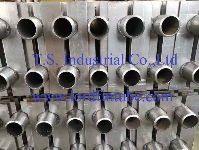
Figure: HH Finned Tube Bundle installed in a waste heat recovery unit.