


Lord Fin Tube-180° Return Bends for Fin Tube
What Are 180° Return Bends for Fin Tubes?
180° return bends for fin tubes are specialized components used in finned tube heat exchangers. These precision-engineered bends facilitate the smooth and efficient flow of fluids or gases through the finned tube system while accommodating thermal expansion and contraction of the tubes due to temperature variations.
The 180° return bends are typically installed at the ends of finned tubes to redirect the flow of fluid or gas back in the opposite direction, creating a compact U-shaped configuration. These essential components are critical for applications with space constraints or specific piping arrangements requiring efficient, space-saving designs.
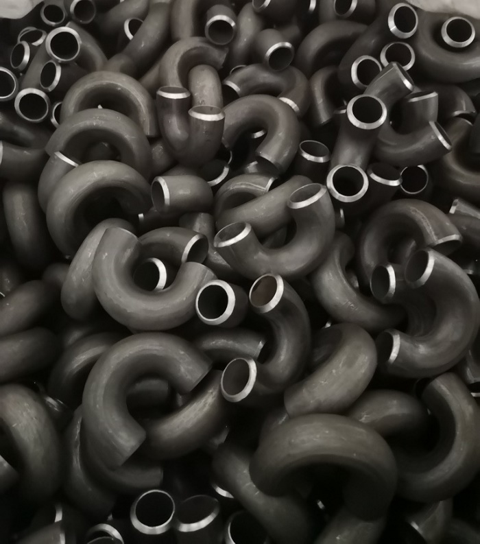
180° Return Bends for Fin Tube
How 180° Return Bends Work in Heat Exchange
Within a finned tube heat exchanger, the 180° return bends serve as the turning points that reverse the flow direction of the heating or cooling medium. As the fluid travels along a finned tube, it absorbs or releases thermal energy through the extended surface area provided by the fins. When the fluid reaches the end of the tube, the 180° return bend redirects it into the adjacent tube, allowing the fluid to continue its heat exchange journey in the opposite direction.
This U-turn flow pattern effectively doubles the heat transfer path within a compact footprint. The smooth internal geometry of a well-manufactured 180° return bend minimizes turbulence and pressure loss, ensuring that the fluid maintains its velocity and thermal exchange efficiency. Why does this matter? Because even minor flow disruptions can reduce overall heat transfer rates and increase pumping costs in large-scale systems.
Key insight: The performance of a finned tube heat exchanger depends significantly on the quality and precision of its 180° return bends. Poorly formed bends can create flow restrictions, hot spots, and premature tube failure.
Which Materials Are Used for 180° Return Bends
The bends are typically manufactured from the same material as the finned tubes themselves. Material selection depends on specific application requirements including temperature range, pressure conditions, and corrosion resistance needs.
| Material Type | Specifications | Applications |
|---|---|---|
| Carbon Steel | ASTM/ASME A234 WPB, WPC | General purpose applications, moderate temperatures |
| Alloy Steels | ASTM/ASME A234 WP 1-WP 12-WP 11-WP 22-WP 5-WP 91-WP911, 15Mo3 15CrMoV | High-temperature applications, power generation |
| Stainless Steel | ASTM/ASME A403 WP 304-304L-304H-304LN-304N, 316-316L-316H-316LN-316N-316Ti, 321-321H, 347-347H | Corrosive environments, food processing, chemical industry |
| Low Temperature Steel | ASTM/ASME A402 WPL3-WPL 6 | Cryogenic applications, refrigeration systems |
| High Performance Steel | ASTM/ASME A860 WPHY 42-46-52-60-65-70 | High-pressure applications, specialized industrial uses |
Beyond the standard materials listed above, custom alloys and clad materials can be specified for extreme service conditions. Which material is right for your project? That depends on the operating environment, the fluid being handled, and the expected service life of the equipment. For example, stainless steel 316L offers excellent resistance to chloride pitting, making it a preferred choice for marine or chemical processing applications where 180° return bends must withstand aggressive media.
Material Performance Comparison
| Material | Max Operating Temp (°C) | Corrosion Resistance | Typical Industries |
|---|---|---|---|
| Carbon Steel | 425 | Moderate | HVAC, general industrial |
| Alloy Steel (P91) | 600 | Good | Power generation, petrochemical |
| Stainless 304 | 800 | Excellent | Food processing, pharmaceuticals |
| Stainless 316 | 800 | Superior | Chemical, marine, offshore |
| Low Temp Steel | -45 | Moderate | Cryogenic, refrigeration |
Why 180° Return Bends Matter in System Design
The choice and quality of 180° return bends directly influence the reliability, efficiency, and longevity of a finned tube heat exchanger. Here is why they deserve careful attention during the design and procurement phases:
- Thermal performance: Properly designed bends maintain the velocity profile of the fluid, ensuring consistent heat transfer coefficients across the entire tube bundle.
- Mechanical integrity: High-quality bends reduce stress concentrations at the tube-to-bend junctions, minimizing the risk of fatigue cracking under cyclic thermal loads.
- Maintenance accessibility: Well-configured return bends allow for easier cleaning and inspection of the tube internals, which is critical for fouling-prone services.
- Space efficiency: The compact U-turn configuration enabled by 180° return bends allows designers to pack more heat transfer surface into a given floor area or enclosure.
Design Impact
180° return bends determine the overall footprint of the heat exchanger. A well-designed bend with minimal centerline radius reduces the overall bundle length, which can translate into significant savings in structural steel, piping, and installation costs.
Operational Impact
During operation, the return bends experience thermal cycling as the system heats up and cools down. Bends manufactured with appropriate wall thickness and material ductility can accommodate these expansions without developing stress cracks or leaks.
Where 180° Return Bends Are Applied
Heat Exchangers
Widely used in shell and tube heat exchangers for efficient fluid direction and compact design.
Boiler Systems
Essential components in boiler systems for redirecting flow and maximizing heat transfer efficiency.
HVAC Systems
Critical for air conditioning and refrigeration systems where space optimization is crucial.
Power Generation
Used in power plants for heat recovery steam generators and other thermal systems.
Additional application areas include oil and gas processing, chemical reactors, waste heat recovery units, and district heating networks. In each of these settings, 180° return bends for fin tubes play a vital role in maintaining process temperatures, improving energy utilization, and ensuring safe, continuous operation.
How to Select the Right 180° Return Bends
When selecting 180° return bends for fin tubes, consider these critical factors:
- Operating Temperature Range: Ensure material selection matches the temperature requirements of your application.
- Pressure Rating: Verify that the bend specifications meet or exceed system pressure demands.
- Fluid Compatibility: Select materials resistant to corrosion from the process fluid.
- Thermal Expansion: Account for differential expansion between tubes and bends in system design.
- Installation Requirements: Consider connection methods and accessibility for maintenance.
- Bend Radius: Choose between short-radius and long-radius bends based on space constraints and flow requirements.
- Wall Thickness: Match the bend wall thickness to the tube wall thickness to ensure consistent strength and flow characteristics.
For a more structured approach, the following table summarizes key selection criteria and their impact on performance:
| Selection Factor | What to Evaluate | Impact on System |
|---|---|---|
| Material grade | Compatibility with fluid, temperature, and pressure | Corrosion resistance, service life |
| Bend radius | Short (1D) vs long (1.5D or more) | Pressure drop, space usage, fabrication cost |
| Wall thickness | Schedule 40, 80, or custom | Strength, weight, thermal response |
| Surface finish | Internal smoothness, external coating | Flow efficiency, corrosion protection |
| Connection type | Butt weld, socket weld, threaded | Installation ease, leak integrity |
What Makes 180° Return Bends Reliable
Enhanced Heat Transfer Efficiency
The design of return bends prioritizes smooth internal surfaces and proper alignment with adjacent tubes, maintaining optimal flow dynamics and heat transfer characteristics.
System Integrity and Longevity
180° return bends are engineered to withstand demanding operating conditions including high temperatures, pressure fluctuations, and vibrational stresses, ensuring reliable long-term performance.
Space Optimization
The compact U-shaped configuration allows for efficient use of available space, making these components ideal for applications with spatial constraints.
Improved Flow Dynamics
Precision engineering minimizes flow resistance and pressure drop, contributing to overall system efficiency.
Beyond these core benefits, modern manufacturing techniques such as induction bending and cold bending with mandrel support have further enhanced the reliability and consistency of 180° return bends. These processes reduce wall thinning and ovality, ensuring that every bend meets the stringent requirements of ASME and ASTM standards.
Dimensional Standards and Tolerances
The dimensions of return bends must precisely match the outer diameter and wall thickness of the finned tubes to ensure proper fitment and seamless integration into the heat exchange system. Custom sizing is available to meet specific application requirements.
| Nominal Size | Outside Diameter (mm) | Wall Thickness Range (mm) | Centerline Radius (mm) |
|---|---|---|---|
| 1/2" | 21.3 | 2.11 – 3.73 | 38 |
| 3/4" | 26.7 | 2.11 – 3.91 | 48 |
| 1" | 33.4 | 2.77 – 4.55 | 60 |
| 1-1/4" | 42.2 | 2.77 – 4.85 | 76 |
| 1-1/2" | 48.3 | 2.77 – 5.08 | 89 |
| 2" | 60.3 | 2.77 – 5.54 | 114 |
For non-standard sizes or special wall thickness requirements, custom fabrication is available. It is important to communicate the exact tube dimensions and the desired bend radius to the manufacturer to ensure a precise fit and optimal performance.
Manufacturing Process of 180° Return Bends
The manufacturing process involves specialized bending techniques that carefully form the tube to a perfect 180° angle without causing deformation or damage to the tube structure or fins. This precision bending maintains the integrity and performance characteristics of the finned tube.
Key steps in the manufacturing process include:
- Tube preparation: Cutting the straight tube to length and cleaning the surfaces to remove any contaminants that could affect the bending process.
- Bending operation: Using a mandrel or filler material to support the tube internally during bending, preventing collapse or wrinkling.
- Heat treatment: Applying appropriate thermal cycles to relieve residual stresses and restore the materials mechanical properties.
- Finishing: Grinding, polishing, or coating the bend surfaces to achieve the required surface finish and corrosion protection.
- Inspection: Performing dimensional checks, wall thickness measurements, and non-destructive testing (NDT) to verify quality.
Advanced manufacturers employ CNC-controlled bending machines that can produce highly consistent bends with tight tolerances. This level of precision is particularly important when the return bends are part of a large tube bundle where alignment and spacing must be uniform.
Installation and Maintenance of 180° Return Bends
The ends of 180° return bends are engineered for compatibility with various connection methods including welding, brazing, or mechanical connections. This ensures secure, leak-free integration with adjacent components in the heat exchanger system.
During installation, consider the following best practices:
- Alignment: Ensure that the bend axis aligns precisely with the adjacent tube axis to avoid imposing bending stresses on the weld joints.
- Welding procedure: Use qualified welding procedures that match the base material and thickness. Preheat and post-weld heat treatment may be required for certain alloys.
- Support: Provide adequate support for the tube bundle to prevent sagging or misalignment over time, especially in horizontal installations.
- Inspection after installation: Perform a visual inspection and, where applicable, hydrostatic or pneumatic testing to verify the integrity of all joints.
For ongoing maintenance, regular inspections should focus on:
- Checking for signs of erosion or corrosion at the bend intrados (inner curve) and extrados (outer curve).
- Monitoring for vibration-induced fatigue cracks near the weld zones.
- Measuring wall thickness periodically to detect thinning caused by flow-accelerated corrosion or erosion.
- Cleaning the internal surfaces to remove fouling deposits that can reduce heat transfer efficiency.
Common Questions About 180° Return Bends
Short-radius bends have a centerline radius equal to the nominal pipe size (1D), while long-radius bends have a radius of 1.5 times the nominal size (1.5D). Short-radius bends are more compact but create higher pressure drop and may have greater wall thinning. Long-radius bends offer smoother flow and less stress concentration, making them preferable for high-pressure or high-temperature services.
The required wall thickness is determined by the design pressure, temperature, and the allowable stress of the material at the operating temperature. ASME B31.3 and ASME Section VIII provide calculation methods. As a general rule, the bend wall thickness should be at least equal to the tube wall thickness, and often slightly thicker in the extrados region to compensate for thinning during bending.
Common failure mechanisms include stress corrosion cracking (SCC), thermal fatigue, erosion-corrosion, and vibration-induced fatigue. These can often be traced back to improper material selection, inadequate wall thickness, poor weld quality, or insufficient support. Selecting the right material and following proper installation procedures are key to avoiding premature failure.
In some cases, minor leaks at the weld joints can be repaired by re-welding or by applying a repair sleeve. However, if the bend itself has cracked or thinned significantly, replacement is usually the safer and more cost-effective option. Regular inspection and monitoring can help catch issues early before they lead to catastrophic failure.
The most common standards are ASTM A234 (for carbon and alloy steel fittings), ASTM A403 (for stainless steel fittings), and ASME B16.9 (for factory-made wrought steel butt-welding fittings). These standards define dimensional tolerances, material requirements, and testing procedures. Always verify that your suppliers products comply with the relevant standards for your jurisdiction and application.
180° elbows for finned tubes (also known as U-bend finned tubes) are essential components in various heat exchange systems. These specialized finned tubes significantly increase the heat transfer area, improving overall heat exchange efficiency, and are particularly valuable in applications with space limitations.
When sourcing 180° return bends for fin tubes, it is essential to work with a reputable manufacturer who can provide full material traceability, dimensional certification, and testing documentation. This ensures that the components you receive meet the stringent requirements of your heat exchange system and contribute to its reliable, long-term operation.