

Lord Fin Tube-Furnace Studded Tube|Studded Pipe
Furnace Studded Tube Technology: Design, Specifications, and Industrial Applications
Furnace studded tubes represent a critical innovation in heat transfer technology, specifically engineered to maximize thermal efficiency in high-temperature industrial applications. These specialized components feature strategically welded pin fins that significantly enhance surface area and improve heat exchange rates.
Furnace Studded Tube Fundamentals
A Furnace Studded Tube is manufactured by welding precisely configured studs (pin fins) onto the external surface of a base tube. This engineering solution addresses the fundamental challenge of gas-side heat transfer limitations in furnace applications, where conventional smooth tubes often prove inefficient.
The studded design creates turbulent flow patterns in the flue gas stream, disrupting the boundary layer and facilitating more effective thermal transfer. This results in up to 3-5 times greater heat exchange capacity compared to standard bare tubes, making them indispensable for modern industrial energy recovery systems.
Furnace Studded Tube Principles
In conventional heat exchangers, gas-to-liquid heat transfer faces significant limitations due to the poor thermal conductivity of gases. The studded configuration fundamentally alters this dynamic through three primary mechanisms:
Enhanced Surface Area
Each stud extends the effective heat transfer surface, typically increasing it by 200-400% depending on stud density and configuration.
Boundary Layer Disruption
The staggered stud pattern creates controlled turbulence that breaks up the insulating gas boundary layer adjacent to the tube surface.
Improved Flow Distribution
Studded patterns promote more uniform gas flow across the tube bundle, eliminating hot spots and cold zones that reduce efficiency.
These tubes are particularly effective in waste heat recovery applications from industrial furnaces, boilers, kilns, and chemical processing units where maximizing thermal recovery directly impacts operational costs and environmental compliance.
Furnace Studded Tube Specifications
The following table presents common specifications for furnace studded tubes in industrial applications:
| Parameter | Standard Specification | Common Variations |
|---|---|---|
| Base Tube Outer Diameter | 114.3 mm (4.5 inches) | 60.3 mm - 168.3 mm |
| Base Tube Thickness | 6.02 mm (Schedule 40) | 3.91 mm - 12.7 mm |
| Stud Diameter | 6.35 mm (0.25 inches) | 5 mm - 12 mm |
| Stud Height | 12.7 mm (0.5 inches) | 10 mm - 25 mm |
| Stud Pitch (Circumferential) | 28 studs per round | 20 - 36 studs per round |
| Stud Pitch (Longitudinal) | 24 studs per foot | 16 - 32 studs per foot |
| Base Tube Material | ASTM A106 Gr.B / A335 P5 | Carbon Steel, Alloy Steel, Stainless Steel |
| Stud Material | Carbon Steel / 12% Chrome | 304, 316L, 321, Alloy 625 |
Furnace Studded Tube Materials
Choosing the appropriate material combination for furnace studded tubes depends on operating conditions, corrosion environment, and thermal requirements:
| Application Environment | Recommended Base Tube Material | Recommended Stud Material | Maximum Service Temperature |
|---|---|---|---|
| General Purpose / Low Corrosion | ASTM A106 Gr.B | Carbon Steel | 450°C (842°F) |
| High Temperature / Oxidation Resistance | ASTM A335 P5/P11/P22 | 12% Chrome / 410 Stainless | 650°C (1202°F) |
| Corrosive Flue Gas (Sulfur, Chlorides) | 316L / 317L Stainless | 316L / Alloy 625 | 900°C (1652°F) |
| Extreme Corrosion / Chemical Processing | Duplex 2205 / 2507 | Duplex 2205 / Hastelloy | 300°C (572°F) |
| Very High Temperature Furnaces | 310S / RA 330 / Inconel | 310S / RA 333 | 1200°C (2192°F) |
Furnace Studded Tube Parameters
Pressure Ranges
Furnace studded tubes are designed to operate within specific pressure parameters to ensure safety and longevity:
- Shell Side (Flue Gas Side): ≤ 20 kPa (2.9 psi) - This relatively low pressure reflects typical flue gas conditions in industrial furnaces and boilers.
- Tube Side (Process Fluid Side): ≤ 6.3 MPa (913 psi) - Higher pressure ratings accommodate various process fluids including water, thermal oils, and chemical media.
Temperature Ranges
The operational temperature limits depend on material selection and specific design:
- Maximum Flue Gas Temperature: ≤ 1200°C (2192°F) for high-temperature alloys
- Typical Operating Range: 300-900°C (572-1652°F) for most industrial applications
- Minimum Temperature Considerations: Must remain above dew point to prevent acid condensation in certain flue gases
Furnace Studded Tube Applications
Waste Heat Recovery Boilers
Recovering thermal energy from furnace exhaust gases to generate steam or preheat combustion air, improving overall system efficiency by 10-25%.
Process Heaters & Furnaces
Enhancing heat transfer in fired heaters for petroleum refining, chemical processing, and petrochemical applications where uniform heating is critical.
Cogeneration Systems
Increasing the effectiveness of heat recovery steam generators (HRSGs) in combined cycle power plants through improved gas-side heat transfer.
Flue Gas Desulfurization
Pre-heating flue gases before treatment systems to maintain optimal temperature for chemical reactions and prevent condensation issues.
Glass & Ceramic Kilns
Improving thermal efficiency in high-temperature kilns where maintaining precise temperature profiles directly impacts product quality.
Metallurgical Furnaces
Enhancing heat recovery from non-ferrous metal production processes including aluminum smelting and copper refining operations.
Furnace Studded Tube Selection
When specifying furnace studded tubes, several critical factors must be evaluated:
- Flue Gas Composition: Analyze corrosive elements including sulfur compounds, chlorides, and alkaline components that affect material selection.
- Particulate Loading: Evaluate dust and ash content to determine appropriate stud spacing that minimizes fouling while maintaining heat transfer efficiency.
- Thermal Cycling: Consider frequency and magnitude of temperature variations that impact thermal fatigue resistance.
- Mechanical Requirements: Assess pressure differentials, flow-induced vibrations, and structural support needs.
- Maintenance Access: Plan for inspection, cleaning, and potential replacement requirements throughout equipment lifespan.
Furnace Studded Tube Performance
Enhanced Efficiency
Studded tubes typically achieve 3-5 times greater heat transfer coefficients compared to bare tubes, directly reducing fuel consumption and operating costs.
Compact Design
The increased effectiveness allows for more compact heat exchanger designs, reducing space requirements and structural support needs.
Reduced Fouling
Properly configured stud patterns create self-cleaning effects that minimize particulate accumulation and maintain performance over time.
Extended Service Life
Appropriate material selection and stud welding techniques ensure reliable operation even in aggressive industrial environments.
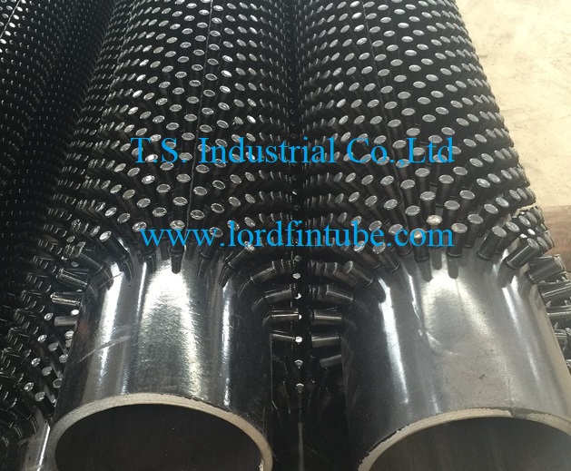
Figure 1: Furnace studded tube installation showing optimized stud pattern for maximum heat transfer efficiency
Furnace Studded Tube Design
Modern furnace studded tube design incorporates computational fluid dynamics (CFD) analysis to optimize several parameters:
- Stud Pattern Configuration: Determining optimal circumferential and longitudinal spacing based on specific flow conditions
- Thermal Stress Analysis: Evaluating temperature gradients and expansion differentials between studs and base tube
- Flow Distribution Studies: Ensuring uniform gas flow across tube banks to prevent localized overheating or underperformance
- Erosion Prediction: Modeling particulate flow paths to identify and mitigate potential wear points
These advanced engineering approaches ensure that each studded tube installation is precisely tailored to its specific operating conditions, maximizing both performance and longevity.
Furnace Studded Tube Maintenance
Proper installation and maintenance practices significantly impact the performance and lifespan of furnace studded tube systems:
- Handling Precautions: Protect studded surfaces during transportation and installation to prevent damage to the welded studs
- Cleaning Protocols: Establish regular cleaning schedules based on specific fouling characteristics of the application
- Inspection Procedures: Implement routine visual and non-destructive testing to identify potential issues early
- Performance Monitoring: Track key parameters including temperature differentials and pressure drops to detect efficiency degradation
- Repair Methodologies: Develop approved procedures for in-situ stud replacement or repair when necessary
When properly specified, installed, and maintained, furnace studded tubes deliver reliable, efficient performance in demanding industrial applications, contributing significantly to energy conservation and operational cost reduction.