

Introduce Types of Baffles in Heat Exchanger
Classification of Heat Exchanger Baffles
In shell and tube heat exchangers, the tube sheet and baffles are two distinct yet equally vital components.
The tube sheet is a thick, precision-drilled plate that serves as the foundation, securely anchoring the ends of the tubes and separating the shell-side and tube-side fluids. Baffles, on the other hand, are a series of plates (or other structures) installed within the shell. Their primary function is not sealing, but flow direction—they guide the shell-side fluid across the tube bundle in a specific pattern to maximize heat transfer efficiency, support the tubes to prevent vibration, and influence pressure drop. In short, the tube sheet is the static backbone, while baffles are the dynamic directors of shell-side performance.
As a specialized manufacturer of tube sheets and baffles, we provide an in-depth analysis of the primary baffle types, their configurations, and applications to help you optimize your thermal systems.
1. Longitudinal Baffles
A longitudinal baffle is typically a rectangular steel plate whose width is slightly less than the shells inner diameter. Its length extends from the tube sheet to the opposite end of the shell section, effectively dividing the shell cross-section into two or more longitudinal flow passes.
Its primary advantage is enabling a true counter-current flow pattern in multi-pass shell designs (such as TEMA F, G, or H types). This achieves a closer temperature approach between the hot and cold fluids compared to arrangements with only transverse baffles, significantly boosting thermal efficiency. It is commonly used in applications requiring precise temperature control or high thermal effectiveness.
Processing Difficulty & Applications
Processing Difficulty: Relatively straightforward
Application: Used for two pass shell heat exchanger

The longitudinal baffle should have sufficient rigidity, with a minimum thickness of 6mm. If the shell-side pressure drop is significant, the thickness should be increased accordingly.
The sealing of the longitudinal baffle includes sealing at two locations: between the baffle and the tube sheet, and between the baffle and the shell body.
(1) Connection between the longitudinal baffle and the tube sheet
The connection between the longitudinal baffle and the tube sheet can be either a removable connection or a welded connection.
Removable connection:
a. Through fasteners: The structure is slightly complex, and since heat exchanger vibration is unavoidable, bolt connections are prone to loosening.
b. Through sealing gaskets: Similar to the connection between the tube box partition baffle and the tube sheet. It should be noted that the longitudinal baffle and the tube sheet, and the shell body cannot both use removable connections simultaneously, otherwise the seal cannot be guaranteed.

Welded connection
This is the most widely used connection method, simpler and more reliable than the previous two.

(2) Connection between the longitudinal baffle and the shell body
Two types of removable connections and two types of welded connections:
a. Through elastic sealing strips
This is currently the most common sealing method used in double-shell heat exchangers.
b. Suitable for large-diameter fixed tube sheet heat exchangers
Requiring pre-welding into the shell, making assembly more difficult.
c. Numerous cases of shell-side fluid short-circuiting have occurred
Showing obvious drawbacks, and it is generally not used.
d. Suitable for low-pressure structures and small-diameter equipment
Where internal welding is not possible. This structure generates edge stress at the connection point, and welding defects are easily formed at the root of the weld between the baffle and the shell, posing a quality risk.

(3) Connection between the longitudinal baffle and the baffle plate
The connection between the longitudinal baffle and the baffle plate should use double-sided welding.
Material Selection
Material is typically matched to the shell and tube sheet (e.g., carbon steel, stainless steel, duplex steel) to ensure uniform corrosion resistance and weldability.
2. Transverse Baffles
These baffles are installed perpendicular to the tube axis, creating a series of windows for fluid to flow across the tubes. They are the most common type.
(1) Segmental Baffles
① Single Segmental Baffles
a. Horizontal
Advantage: Excellent heat transfer, good mechanical tube support.
Application: The most versatile, widely used in liquid-liquid and liquid-gas services.
b. Vertical
Advantage: Facilitates condensate drainage, reduces liquid holdup.
Application: Primarily in shell-side condensers and reboilers.
c. Rotated
Advantage: Reduces dead zones and fouling compared to horizontal cuts, smoother flow distribution.
Application: Services prone to fouling or where lower vibration is desired.

| Type | Horizontal | Vertical | Rotated |
|---|---|---|---|
| Advantage | Excellent heat transfer, good mechanical tube support | Facilitates condensate drainage, reduces liquid holdup | Reduces dead zones and fouling compared to horizontal cuts, smoother flow distribution |
| Application | The most versatile, widely used in liquid-liquid and liquid-gas services | Primarily in shell-side condensers and reboilers | Services prone to fouling or where lower vibration is desired |
Material Selection for Single Segmental Baffles
Most common materials (CS, SS, etc.). For corrosive services, cladding or full alloy baffles are used.
② Double Segmental Baffles
a. Split baffle
In case of double segmental baffles, significantly lower pressure drop (approx. 1/8 to 1/4 of single segmental) for similar heat transfer, reduced vibration risk.
Ideal for low-pressure-drop requirements Gas cooling/heating Large diameter exchangers
b. Centre baffle
An extension of the double segmental concept, using three baffle segments per baffle plane.
Highest processing difficulty among segmental types

③ Triple Segmental Baffles
Advantages: Even lower pressure drop than double segmental.
Applications: Very low-pressure-drop applications, often in air or gas coolers.
Processing Difficulty: Highest among segmental types due to complexity

(2) Disc and Ring Baffles
This design consists of two alternating baffle types mounted on a central rod: Doughnut + disc structure.
Fluid alternately flows through the annular gap around the disk and the central hole of the doughnut. This creates a more uniform velocity profile and can handle high-flow, low-fouling services with relatively low pressure drop.
Design Advantages
Creates a more uniform axial/radial flow, good for high velocity gases, lower fouling tendency in some services compared to segmental.
Applications
High-capacity gas heat exchangers Some feedwater heaters Services where low fouling and moderate pressure drop are needed

(3) Orifice Baffles
Orifice baffles are plates with holes drilled slightly larger than the tube O.D. The shell-side fluid flows through the gaps between the baffle plates and the tubes to increase heat transfer efficiency.
This type of baffle plate has a high pressure drop and is only suitable for relatively clean fluids.
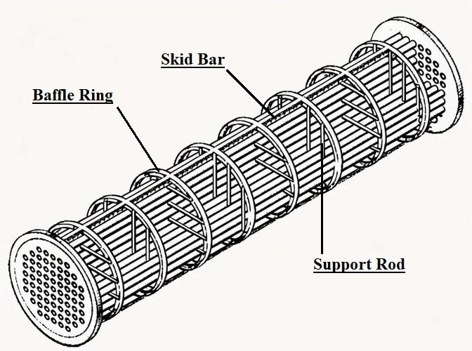
(4) Rod Baffles
This design does not use plates, but instead consists of interlocking thin strip-like rod components, forming a square or rhombic grid-like support structure. This structure, combined with deflection rings and multiple deflection rods, provides gap-free support, making it easy to install and remove the corrugated tubes.
Tubes are supported at multiple points by these rods, which are held in place by grids. The flow is essentially longitudinal with minimal obstruction, resulting in an extremely low pressure drop, excellent resistance to tube vibration, and reduced fouling tendency.
Design Advantages
- Shell-side pressure drop is reduced by more than 50% compared to traditional baffle plates
- Eliminates heat transfer dead zones and slows down fouling rate
- Small contact area between the rods and heat exchange tubes allows for full utilization
- Excellent vibration resistance prevents heat exchange tube breakage
- Improved manufacturing process optimizes appearance and reduces costs
Applications
The rod baffles are ideal for gas cooling/heating and viscous fluid services.
In rod baffle heat exchangers, the rod baffles are typically arranged along the length of the tube bundle at fixed intervals. The key feature is that the orientation of the support rods in adjacent rod baffles alternates. Typically, the support rods on one rod baffle are vertically oriented, while on the immediately adjacent baffle, they are rotated 90 degrees to a horizontal orientation. This vertical-horizontal alternating arrangement extends throughout the entire tube bundle area.
3. Helical Baffles
Helical baffles create a smooth, swirling, helical flow path for the shell-side fluid, mimicking ideal plug flow. This eliminates the dead zones and high turbulence associated with segmental baffles.
(1) Continuous Helical Baffle
Formed from a continuous, twisted strip or specially shaped plates that create an unbroken helical channel. It offers the lowest pressure drop and fouling rate for a given heat duty but is complex and costly to manufacture.
Advantages: Smoothest helical flow, lowest pressure drop and fouling potential, high thermal efficiency.
Applications: Severe fouling services, where pressure drop is critical, and for viscous fluids.
Processing Difficulty: Very high
Material Selection
Requires materials with good formability.

(2) Non-Continuous Helical Baffle
Constructed from multiple quadrilateral-shaped plate segments, each angled and arranged in a staircase pattern to approximate a helical flow. More practical to manufacture than the continuous type, it still delivers superior performance in reducing pressure drop, vibration, and fouling compared to traditional segmental baffles.
Advantages: Achieves most benefits of helical flow (reduced fouling & vibration, lower ΔP than segmental) with much-improved manufacturability.
Applications: Becoming the preferred choice for fouling services and efficiency upgrades.
Processing Difficulty: Moderate to High
Material Selection
Same as standard plate materials.

FAQ: Parameters for Baffle Plate Design
1. Baffle Cut for Segmental Baffles
Baffle Cut h
Generally 0.2 to 0.45 times the inner diameter of the shell-side cylinder.
The height of the baffle plates arc-shaped notch should be such that the fluid velocity through the notch is similar to the velocity of the fluid flowing transversely across the tube bundle.
Notch height h
Generally 0.2 to 0.45 times the inner diameter of the shell-side cylinder.
The height of the baffle plates arc-shaped notch should be such that the fluid velocity through the notch is similar to the velocity of the fluid flowing transversely across the tube bundle.
2. V-shaped notch of the Segmental baffle plate
(1) Position:
When the shell side of a horizontal heat exchanger contains a single-phase clean fluid, the baffle plate notches should be arranged horizontally, facing upwards and downwards;
- a. When the gas contains a small amount of liquid, a liquid outlet should be opened at the lowest point of the baffle plate with the notch facing upwards.
- b. When the liquid contains a small amount of gas, a gas outlet should be opened at the highest point of the baffle plate with the notch facing downwards.
- c. When the shell-side medium of a horizontal heat exchanger, condenser, and reboiler is a mixture of gas and liquid phases or the liquid contains solid particles, the baffle plate notches should be arranged vertically, facing left and right; when gas and liquid phases coexist, liquid and gas outlets should be opened at the lowest and highest points of the baffle plate.
- d. When the liquid contains solid particles, a liquid outlet should be opened at the lowest point of the baffle plate.

(2) Notch height
Generally 15-20mm
(3) Notch angle
90°
3. Baffle Spacing
- (1) The baffles at both ends of the tube bundle should be as close as possible to the shell-side outlet nozzle, and the remaining baffles should be arranged at equal intervals.
- (2) The baffle spacing should be determined based on the flow rate and viscosity of the shell-side medium.
- (3) The minimum spacing should generally not be less than Di/5, and not less than 50mm.
4. Baffle Fixing Method
(1) Standard Fixing
The baffles are fixed by tie rods and spacer tubes. The thread at one end of the tie rod is screwed into the tube sheet, the baffle is positioned by the spacer tube, and the last baffle is fixed by the nut at the end of the tie rod.
(2) Alternative Methods
Some systems also use a combination of threaded and welded connections or a fully welded connection structure.
