

U bend heat exchanger tube ASME SA213 TP316L
U Bend Heat Exchanger Tube ASME SA213 TP316L
U Bend heat exchanger tubes manufactured from ASME SA213 TP316L material represent a specialized component in thermal management systems. These bent tubes facilitate optimal heat transfer in constrained spaces while maintaining structural integrity under demanding conditions. The unique U-shaped configuration allows for thermal expansion accommodation and efficient fluid dynamics within compact heat exchanger designs.
U Bend Heat Exchanger Tube Material Composition
The TP316L stainless steel specification provides distinct advantages for U bend tube applications. This low-carbon austenitic stainless steel contains molybdenum, which significantly enhances corrosion resistance in chloride environments and acidic conditions. The material maintains excellent mechanical properties across a temperature range from cryogenic to elevated operating conditions.
| Element | Percentage | Functional Benefit |
|---|---|---|
| Carbon | 0.03% max | Reduces carbide precipitation during welding |
| Chromium | 16-18% | Provides oxidation and corrosion resistance |
| Nickel | 10-14% | Maintains austenitic structure and ductility |
| Molybdenum | 2-3% | Enhances resistance to pitting and crevice corrosion |
| Manganese | 2% max | Improves hot working characteristics |
U Bend Heat Exchanger Tube Manufacturing Process
Creating reliable U bend tubes requires precise manufacturing control. The bending process must maintain uniform wall thickness while achieving accurate radius dimensions. Cold bending techniques are typically employed for TP316L material to prevent sensitization and maintain corrosion resistance properties throughout the bent section.
Bending Radius Standards
The minimum bending radius varies according to tube diameter and wall thickness. Standard practice maintains a minimum radius of 1.5 times the tube outer diameter. For thin-walled applications, specialized mandrel bending ensures deformation control and prevents ovality beyond acceptable limits of 8% of nominal diameter.
Surface Finish Requirements
Internal and external surface finish directly impacts heat transfer efficiency and corrosion resistance. Standard finishes include mechanically polished surfaces with Ra ≤ 0.8 μm for enhanced flow characteristics. Electropolishing options are available for applications requiring superior cleanability and reduced fouling potential.
U Bend Heat Exchanger Tube Performance Characteristics
The U bend heat exchanger tube configuration offers several operational advantages over straight tube designs. The continuous U-shaped path eliminates the need for tube-to-tubesheet joints at both ends, reducing potential leak points. This design accommodates differential thermal expansion between the tube bundle and shell without creating excessive stress concentrations.
Thermal Efficiency Factors
- Enhanced Turbulence: The U bend induces secondary flow patterns that increase fluid mixing, improving heat transfer coefficients by 15-25% compared to straight tube sections under similar flow conditions.
- Compact Footprint: U bend configurations allow approximately 40% more heat transfer surface within the same envelope dimensions compared to removable bundle designs with straight tubes.
- Reduced Pressure Drop: Properly designed U bend geometries minimize pressure loss while maintaining thermal performance, with typical additional pressure drop of only 10-15% compared to equivalent straight tube lengths.
Mechanical Reliability Considerations
U bend sections experience higher stress concentrations compared to straight tube segments. TP316L material provides excellent fatigue resistance with endurance limits suitable for vibrational loading common in heat exchanger applications. The materials strain-hardening characteristics help the bent region maintain dimensional stability under cyclic thermal stresses.
U Bend Heat Exchanger Tube Industry Applications
Chemical Processing Systems
Chemical reactors, condensers, and reboilers utilize U bend configurations for services involving temperature gradients and aggressive media. The seamless construction of U bend tubes prevents contamination risks in high-purity processes. Chloride stress corrosion cracking resistance makes TP316L particularly suitable for processes involving brackish cooling water or chloride-containing process streams.
Power Generation Equipment
Surface condenser and feedwater heater applications benefit from U bend tube arrangements where thermal cycling occurs regularly. The design accommodates differential expansion between the tube bundle and condenser shell during startup and shutdown cycles. TP316L provides adequate resistance to steam erosion and flow-accelerated corrosion in high-velocity sections.
Oil Refining Operations
Refinery heat exchangers processing crude oil fractions and intermediate streams often employ U bend tube designs for maintenance accessibility. The configuration allows for back-flushing capabilities without tube bundle removal. Sulfide stress cracking resistance and chloride pitting resistance make TP316L suitable for refinery cooling water services and certain hydrocarbon processing applications.
U Bend Heat Exchanger Tube Selection Criteria
| Design Parameter | Consideration | TP316L Advantage |
|---|---|---|
| Operating Temperature | Continuous service up to 870°C (1600°F) | Maintains strength and oxidation resistance |
| Corrosive Environment | Chloride concentration & pH levels | Superior pitting resistance compared to 304/304L |
| Thermal Cycling | Frequency of temperature changes | High thermal fatigue resistance |
| Pressure Conditions | Internal and external pressure differentials | Excellent creep resistance at elevated temperatures |
| Cleaning Requirements | Mechanical or chemical cleaning frequency | Good resistance to cleaning solutions and abrasion |
When specifying U bend heat exchanger tubes, dimensional tolerances should align with TEMA standards for shell-and-tube heat exchangers. Critical dimensions include bend radius tolerance (±0.5 mm), tube ovality (<8% of nominal OD), and wall thickness reduction in the bent region (<10% of nominal wall). Proper specification ensures trouble-free installation and optimal thermal performance throughout the service life.
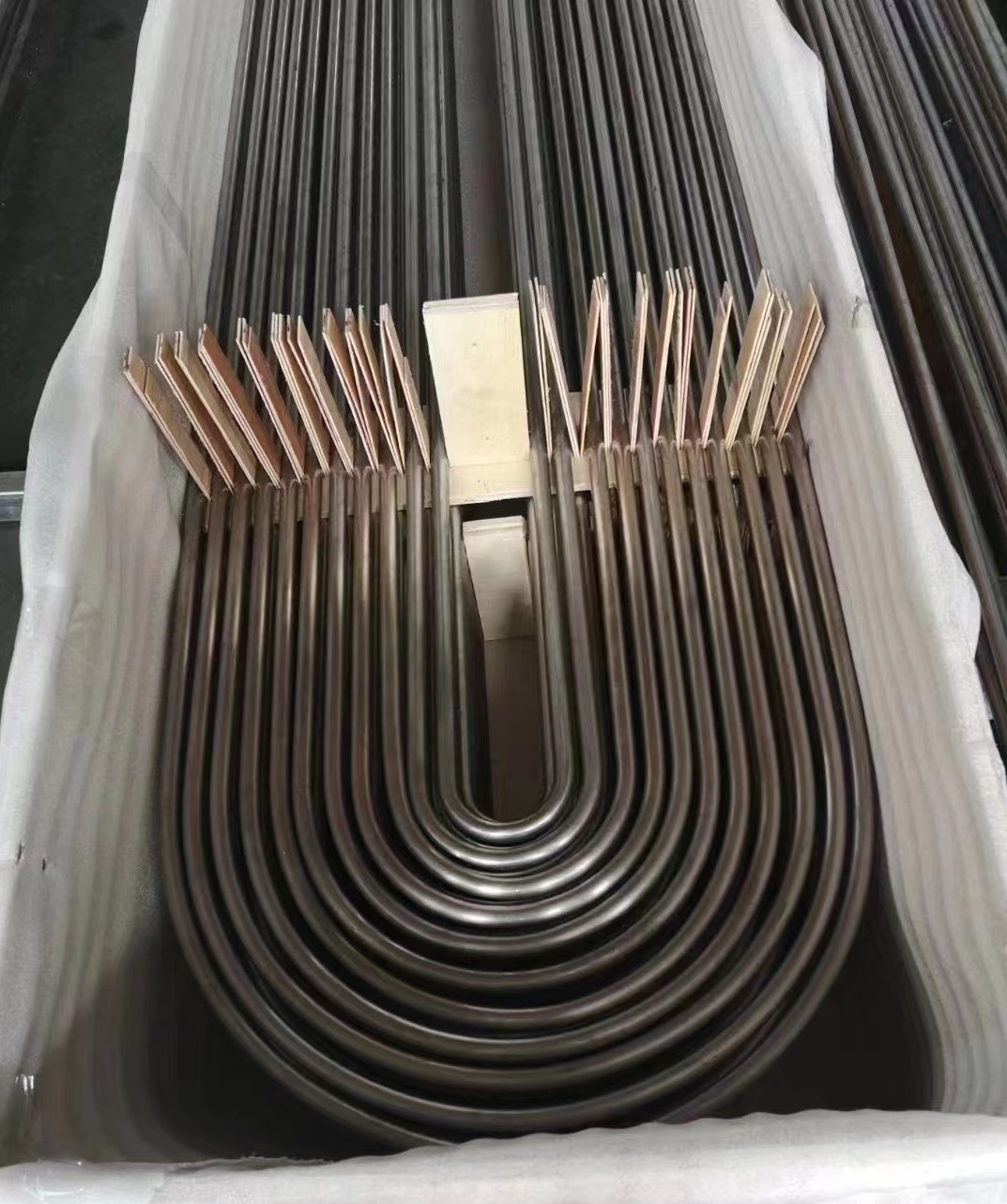
U bend heat exchanger tube ASME SA213 TP316L undergoing dimensional verification and surface inspection
The implementation of U bend configurations in heat exchanger designs continues to expand across process industries. Advances in bending technology and non-destructive examination methods have increased reliability while maintaining cost-effectiveness. Proper material selection, combined with appropriate bending techniques and quality verification, results in durable heat transfer components that deliver consistent performance in demanding operational environments.