“U” Channel finned tube and return bends
"U" channel finned tubes and return bends are components commonly used in heat exchanger systems to enhance heat transfer efficiency. "U" channel finned tubes also called longitudinal finned tubes or Brown Fintube.
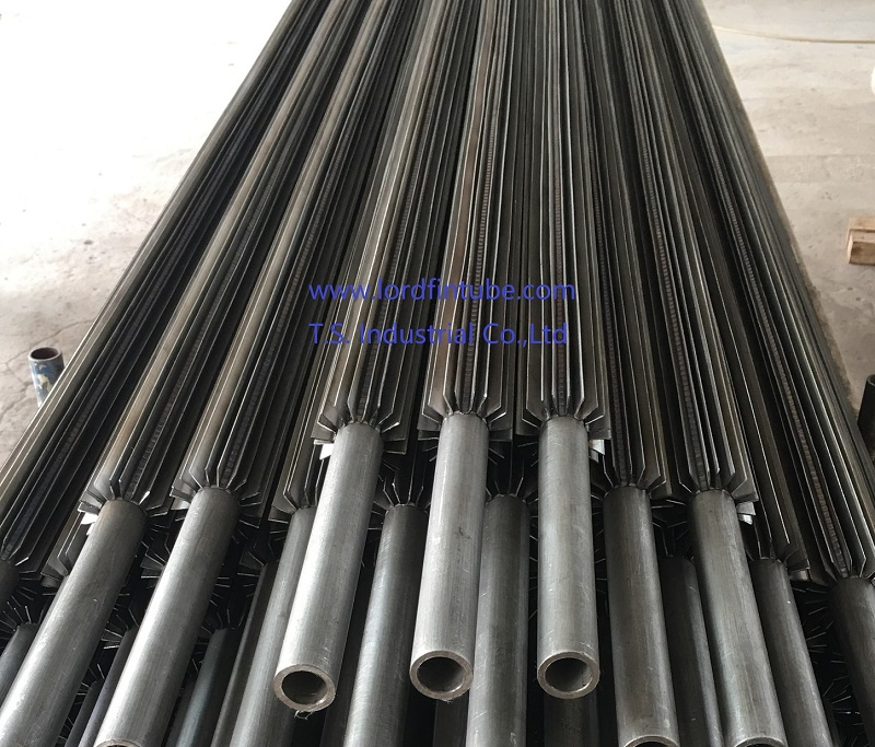
1. "U" Channel Finned Tube:
- Tube: Refers to the basic cylindrical structure that carries the fluid (either liquid or gas) for heat exchange.
- "U" Channel Finned: The term "U" channel indicates the shape of the fins attached to the outer surface of the tube. These fins are typically arranged in a U-shaped configuration along the length of the tube.
- Finned Tube Purpose: Fins increase the surface area of the tube, which improves heat transfer between the fluid inside the tube and the surrounding environment (air or another fluid). This design is especially useful when one of the fluids has a lower heat transfer coefficient.
2. Return Bends:
- Return Bends: These are curved sections of tubing used to change the direction of fluid flow in a heat exchanger. Return bends are often installed at the ends of finned tubes or in the overall design of the heat exchanger system.
- Purpose: Return bends allow the fluid to circulate back through the heat exchanger, ensuring a continuous and efficient heat exchange process.
The combination of "U" channel finned tubes and return bends is commonly found in various heat exchanger applications, including air-cooled heat exchangers, refrigeration systems, and industrial process heat exchangers. The fins increase the heat transfer area, while the return bends facilitate the fluids flow within the system.
This configuration is designed to optimize the efficiency of heat exchange, making it a popular choice in applications where effective temperature control is crucial.
Sample Inquiry of “U” Channel finned tube and return bends
“U” Channel finned tube|Brown fin tubes|Longitudinal finned tubes and return bends as per attached sketch.
Sr # Description Material Quantity
1. “U” Channel finned tube SMLS Tube Ø 1” O.D x BWG 10 (Ø 25.4 x 3.4 mm Thk) x 3550 mm Long.
SA-179 (Nace Compliance) 24 Nos.
Fin Channel “U” 12.7 x 0.9 mm 12 “U” Per Tube, SA-109 ,288 Nos.
1.1 Return Bend Ø 1” x BWG10 C.C 57, SA179 (Nace Compliance), 5
1.2 Return Bend Ø 1” x BWG10 C.C 139 SA179 (Nace Compliance), 4
1.3 Return Bend Ø 1” x BWG10 C.C 227 SA179 (Nace Compliance), 3
2. “U” Channel finned tube SMLS Tube Ø 1” O.D x BWG 10 (Ø 25.4 x 3.4 mm Thk) x 3000 mm Long. SA-179 (Nace Compliance) 18 Nos.
Fin Channel “U” 12.7 x 0.9 mm 12 “U” Per Tube, SA-109 , 216 Nos.
2.1 Return Bend Ø 1” x BWG10 C.C 57 SA179 (Nace Compliance) 4
2.2 Return Bend Ø 1” x BWG10 C.C 104.8 SA179 (Nace Compliance) 1
2.3 Return Bend Ø 1” x BWG10 C.C 141.2 SA179 (Nace Compliance) 2
2.4 Return Bend Ø 1” x BWG10 C.C 193.6 SA179 (Nace Compliance) 2