


A Half-Pipe Coil is a semicircular tube wound helically and welded to the outside of a cylinder, cone, or dished head so that it forms a closed flow channel against the vessel wall. It delivers high heat-transfer rates per unit of vessel surface, tolerates elevated pressures, and can be added to a shell without reducing its internal volume. This article explains how the geometry works, which parameters govern performance, how to size a coil, and where the design reaches its limits.
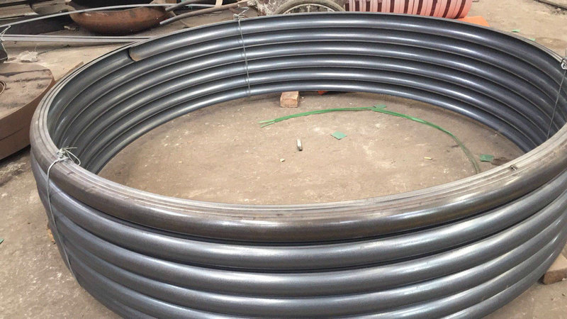
What Is a Half-Pipe Coil and Where Does It Sit on a Vessel?
A half-pipe coil is produced by splitting a tube longitudinally, or by rolling strip into a semicircular section, and then bending that section into a helix. The open face of the section is welded along both longitudinal edges to the shell, head, or cone. The result is a spiral channel of semicircular cross-section whose flat side is the vessel wall itself. Because the wall is part of the channel, heat passes through a single metal thickness between the service fluid and the vessel contents.
The component belongs to the external heat-transfer surface family, together with conventional jackets, dimple jackets, and limpet coils. Unlike a conventional jacket, it does not need a second shell; unlike an internal coil, it does not occupy process volume or interfere with agitators and baffles. In Lordfintubes production range, the helical geometry is formed on Helical Coiled Pipe equipment and then fitted to the customers shell or supplied as a complete assembly.
How the flow channel is formed
- Semicircular section: the tube is deformed to roughly half its original circumference, giving a flat welding face on each side.
- Helical wrap: the section is wound at a fixed pitch around the shell, so adjacent turns are separated by a land that carries the fillet welds.
- Closure: inlet and outlet ports are welded at the ends, and the channel is closed either by a return bend or by a welded end cap.
- Multiple starts: long vessels are often fitted with two, three, or four parallel helices to keep pressure drop inside the pump curve while preserving coverage.
Because each turn is a separate weld pass on both sides, the half-pipe coil is a pressure-retaining attachment. The shell must therefore be checked for local stresses at the weld toes, not only for the hoop stress caused by internal pressure.
How Heat Moves Through a Half-Pipe Coil
Heat crosses four resistances in series: the service-fluid film inside the half-pipe, the vessel wall, the process-side film, and any fouling layers on either side. The half-pipe geometry acts mainly on the first of these. A semicircular channel with a small hydraulic diameter produces high velocity at a modest volumetric flow, which raises the convective coefficient.
Two flow regimes appear in practice. At low flow the channel runs laminar and the coefficient falls quickly as viscosity rises. Above a Reynolds number of roughly 10,000 the flow becomes turbulent and the coefficient stabilises. Helical curvature adds secondary vortices that mildly increase turbulence and shift the transition point, but the effect is smaller than in a full-bore helical coil and should be confirmed by test or by a recognised correlation rather than assumed.
Why the attachment pattern matters
The helix is not a simple tube on a flat plate. Each turn is welded to a curved wall, and the wall conducts heat laterally away from the channel footprint. Wider spacing between turns lets more of the shell area act as a fin, which partially compensates for a coverage ratio below 100%. Conversely, very close spacing concentrates thermal stress at the weld toes and makes external cleaning harder.
Principal Parameters and Their Units
Three parameters dominate every half-pipe coil specification. They are linked: changing one always moves the other two.
Half-pipe diameter (d): the channel bore
Usually specified as the outside diameter in millimetres or as an NPS size. It sets the flow cross-section, the hydraulic diameter, the achievable velocity, and the width of the weld land. A larger diameter lowers pressure drop for a given flow but reduces the number of turns that fit on a given shell length.
Pitch (p): the axial distance between turns
Measured centre-to-centre in millimetres. Pitch controls how much of the shell is covered and how steeply the fluid spirals. Tight pitch raises coverage and heat duty per metre of shell, but it also lengthens the flow path, increases pressure drop, and narrows the gap available for weld access.
Coverage ratio (C): the fraction of shell area in contact
A dimensionless percentage. It expresses how much of the shell circumference is covered by the channel footprint, and it converts shell dimensions into effective heat-transfer area. Coverage, pitch, and half-pipe diameter must be chosen together; specifying two of them fixes the third.
Formulas for Area, Coverage, Velocity, and Pressure Drop
These relationships are used for preliminary sizing. Final values must come from the project specification, the engineers confirmation, and the manufacturers data, because weld geometry, wall conduction, and fouling assumptions vary between designs.
Effective area: A = π × D × L × C
Channel cross-section: Ac = π × d_i² / 8
Wetted perimeter: Pw = (π × d_i / 2) + d_i
Hydraulic diameter: Dh = 4 × Ac / Pw
Mean velocity: v = Qv / Ac
Heat duty: Q = U × A × ΔT_lm
Log mean temperature difference: ΔT_lm = (ΔT1 − ΔT2) / ln(ΔT1 / ΔT2)
Darcy–Weisbach pressure drop: ΔP = f × (L_ch / Dh) × (ρ × v² / 2)
Variable definitions and units: C is dimensionless; w is the axial projection of the half-pipe footprint (mm); p is pitch (mm); D is vessel outside diameter (mm); L is the axial length of the coiled section (mm); A is effective area (m²) after unit conversion; d_i is half-pipe inside diameter (mm); Ac is flow area (mm²); Qv is volumetric flow (m³/s); v is mean velocity (m/s); U is the overall coefficient (W/m²·K); ΔT1 and ΔT2 are terminal temperature differences (K); L_ch is developed channel length (m); f is the Darcy friction factor (dimensionless); ρ is density (kg/m³).
For the convective coefficient, the Dittus–Boelter form is a common starting point: Nu = 0.023 × Re^0.8 × Pr^n, with n = 0.4 for heating and 0.3 for cooling, valid for Re above about 10⁴ and Pr between 0.6 and 160 in straight tubes. Curved and semicircular channels deviate from this, so the result should be treated as indicative. Note also that C is defined differently by different fabricators; some quote coverage against the developed helix length rather than the axial projection. Always confirm which definition a supplier uses before comparing two quotations.
Half-Pipe Coil Compared with Other Jacket and Coil Types
| Aspect | Half-Pipe Coil | Conventional Jacket | Internal Coil | Dimple Jacket |
|---|---|---|---|---|
| Heat transfer coefficient (service side) | High, from small hydraulic diameter | Low to moderate, large open volume | Moderate | Moderate |
| Service-side design pressure | High, typically 10–40 bar | Low, typically 3–10 bar | High | Moderate, typically 6–16 bar |
| Effect on vessel internals | None; external only | None | Occupies volume, obstructs agitation | None |
| Coverage achievable | Moderate, typically 30–70 % | Full wall coverage | Local to coil surface | High, up to 80 % or more |
| External cleaning access | Good, turns are exposed | Good | Requires vessel entry | Good |
| Fabrication and inspection effort | High; double fillet weld per turn | Moderate | Moderate | High; spot-weld pattern |
| Typical use | High-duty heating or cooling of viscous or high-pressure media | General-purpose low-pressure duties | Batch vessels with agitation | Space-limited, moderate duty |
Design Trade-offs: Coverage, Pressure Drop, and Weld Quality
No half-pipe coil is optimal on every axis. The design process is a balance between three competing requirements.
Coverage against pressure drop
Raising coverage increases area and duty, but it also lengthens the flow path. Path length scales roughly as the number of turns, and pressure drop scales with path length and with the square of velocity. Doubling coverage on a fixed shell can therefore double or triple the required pump head. Multi-start helices break the path into parallel streams, which recovers pressure drop without losing coverage, at the cost of more ports and more complex manifolding.
Half-pipe diameter against thermal performance
A small bore gives a high coefficient but a short path and high pressure drop. A large bore gives a low coefficient but generous flow. The usual resolution is to size the bore from the available pump head first, then adjust coverage and pitch to reach the required duty. Selecting a small bore purely to shrink the footprint frequently produces a coil that cannot be fed by the plant utilities.
Pitch against fabrication quality
Tight pitch increases duty density but restricts welder access. Insufficient land between turns leads to overlapping heat-affected zones, poor toe profiles, and higher risk of lack of fusion. A minimum land width is normally set by the fabricator and by the applicable welding procedure. Where duty is high and space is short, the better answer is often a multi-start coil at a workable pitch rather than an aggressive single-start helix.
Pressure rating against wall thickness
The half-pipe wall and the shell wall both carry pressure. Thick walls raise the rating but add conductive resistance and mass, and they stiffen the coil against thermal cycling. Thinner walls need more weld passes to reach the required throat thickness. The rating must be established by calculation to a recognised code, not by comparison with a previous job.
Technical Parameter Table
| Parameter | Unit | Typical range | Design note |
|---|---|---|---|
| Half-pipe outside diameter | mm (NPS) | 25.4–168.3 mm (NPS 1–6) | 48.3, 60.3, and 88.9 mm are common |
| Half-pipe wall thickness | mm | 1.6–6.0 mm | Set by pressure calculation and weld procedure |
| Vessel outside diameter | mm | 300–4000 mm | Larger sizes need engineering review |
| Pitch | mm | 1.5 × d to 4 × d | Must satisfy minimum weld land |
| Coverage ratio | % | 30–70 % | Definition varies by fabricator |
| Design pressure, channel side | bar | 6–40 bar | Code calculation required |
| Design temperature | °C | −196 to 400 °C | Material dependent |
| Effective heat transfer area | m² | 0.5–500 m² | Project specific |
| Internal surface roughness | µm Ra | 0.4–3.2 µm | Hygienic duties typically 0.4–0.8 µm |
Materials and Standards
Material selection is driven by the corrosion behaviour of both fluids, the operating temperature, and the difference in thermal expansion between the half-pipe and the shell. A mismatch in expansion coefficient is a common cause of weld fatigue in cyclic service, so the coil and shell are normally specified as the same family where possible.
| Material family | Common grades | Typical service | Consideration |
|---|---|---|---|
| Austenitic stainless steel | 304 / 304L, 316 / 316L, 321 | Food, pharmaceutical, general chemical | Good weldability; chloride limits apply to 304 |
| Duplex stainless steel | 2205, 2507 | Chloride-bearing cooling water, offshore | Higher strength; ferrite balance must be controlled |
| Carbon steel | ASTM A106, A53 | Steam, hot oil, non-corrosive utilities | Requires external coating and internal treatment |
| Titanium | Grade 2 | Seawater, oxidising media | Excellent corrosion resistance; lower modulus |
| Nickel alloy | Alloy 625, C-276 | Strong acids, high temperature | Cost premium; specialist welding procedure |
Fabrication and design standards vary by market and by vessel type. Commonly referenced documents include the ASME Boiler and Pressure Vessel Code Section VIII for vessel design, ASME B31.3 for process piping, ASTM A249, A269, A312, and A213 for tubular product, EN 13445 for unfired pressure vessels, and the PED 2014/68/EU where CE marking is required. These are listed as typical references only. The governing standard for a given order must be confirmed in the project specification and by the responsible engineer, and the half-pipe coil must not be assumed to comply with a code that has not been explicitly invoked.
Industries and Applications
- Chemical processing: reactor jackets, crystalliser cooling, distillation reboilers, and exothermic reaction control where the jacket must hold elevated pressure.
- Pharmaceutical and bioprocessing: fermenter temperature control and buffer preparation, using hygienic surface finishes and drainable geometry.
- Food and beverage: jacketed process vessels for sauces, dairy, and brewing, where external attachment keeps the interior cleanable.
- Oil, gas, and petrochemical: heat tracing of tanks and lines, glycol cooling, and viscous service heating.
- Energy and environmental: flue-gas reheating, sludge and slurry tanks, and wastewater thermal conditioning.
Two application patterns deserve emphasis. In high-viscosity service the process-side film, not the service side, limits the overall coefficient; adding coverage helps only until the wall resistance becomes dominant. In cyclic service the controlling issue is thermal fatigue at the weld toe, and thicker, stiffer half-pipe is not automatically better.
Selection and Sizing Sequence
- Fix the duty and terminal temperatures. Establish the heat load, both inlet and outlet temperatures, and the permitted pressure drop on each side.
- Identify the controlling resistance. Estimate the process-side and service-side film coefficients before choosing geometry; if the process side dominates, additional coverage yields little.
- Select the half-pipe diameter from available pump head. Confirm that the utility circuit can deliver the resulting flow.
- Set coverage and pitch together to reach the required area while keeping a workable weld land.
- Choose the number of starts. Use parallel helices where path length would otherwise create excessive pressure drop.
- Confirm the pressure rating by code calculation for both the channel and the shell, including local stresses at the attachment.
- Fix materials, surface finish, and any code stamp required by the end users jurisdiction.
- Review maintenance access. Confirm that the pitch and the external insulation detail allow inspection and cleaning over the design life.
Where the vessel also requires an internal exchanger, the two surfaces should be assessed together so that the total area is not simply the sum of two independent estimates. Complementary options such as stainless steel pipe coils and carbon steel pipe coils follow the same sizing logic but differ in corrosion allowance and cleaning requirements.
Quality Control and Testing
Inspection is focused on the two fillet welds that run the full length of the helix, because they are both the pressure boundary and the heat path. Typical checks for a half-pipe coil include:
- Dimensional verification of diameter, pitch, coverage, and overall length against the drawing.
- Visual and penetrant inspection of weld toes, with particular attention to stop-start positions and turn transitions.
- Radiographic or ultrasonic examination where the specification requires it, especially on the closure welds.
- Hydrostatic test of the channel at the specified test pressure, or a pneumatic test with an approved procedure.
- Positive material identification to confirm the delivered grade matches the specification.
- Surface finish measurement on hygienic or high-purity surfaces.
- Ferrite content check on duplex welds, where specified.
The exact test matrix is a project decision. Not every order requires every test, and the scope should be agreed in writing before fabrication rather than assumed.
Packaging, Handling, and Shipping
Half-pipe coils are thin-walled, welded assemblies, and most transit damage comes from point loading and from water ingress into an open channel.
- All channel ends are capped or sealed before dispatch, and the caps stay in place until installation.
- The coil rests on saddles or a fitted cradle; slings pass around the shell, never through the channel.
- Exposed weld toes are protected against impact with a removable wrap or timber batten where handling risk is high.
- Carbon steel surfaces receive a temporary protective coating, and stainless surfaces are kept free of carbon steel contact.
- Sea freight is packed with desiccant and a sealed liner where the route involves high humidity.
Specific packing, marking, and lifting requirements should be confirmed with the manufacturer at order stage, since they depend on size, weight, and destination.
Frequently Asked Questions
What is a half-pipe coil?
A half-pipe coil is a semicircular tube bent into a helix and welded to the outside of a vessel, so that the vessel wall closes the channel. The service fluid flows through the spiral passage while heat passes through the shell wall into or out of the vessel contents.
What is the difference between a half-pipe coil and a conventional jacket?
A conventional jacket surrounds the vessel with a second shell and a large open volume, so it operates at low pressure and low fluid velocity. A half-pipe coil forms a narrow channel, which produces high velocity and a high coefficient at modest flow, and it can hold significantly higher pressure. Coverage is lower than a conventional jacket, but the duty per unit of covered area is much higher.
How is half-pipe coil heat transfer area calculated?
Multiply the vessel circumference by the axial length of the coiled section, then multiply by the coverage ratio: A = π × D × L × C. The coverage ratio is the axial projection of the half-pipe footprint divided by the pitch. Because fabricators define coverage differently, confirm the definition before comparing area figures from two suppliers.
What half-pipe diameter and pitch should I choose?
Size the diameter from the available pump head first, then set pitch and coverage to reach the required duty while leaving enough land for a sound weld. Typical practice is a pitch of one and a half to four times the half-pipe diameter, with coverage between 30 % and 70 %. Final values must be confirmed by calculation and by the manufacturer.
Which materials are used for half-pipe coils?
Austenitic stainless steels such as 304L and 316L are the most common, with duplex stainless steel for chloride-bearing cooling water, carbon steel for steam and hot oil, and titanium or nickel alloys for aggressive media. The coil and the shell are usually specified in the same material family to limit differential thermal expansion.
Can a half-pipe coil be used for both heating and cooling?
Yes. The same channel can carry steam, hot oil, chilled water, or glycol. Switching between heating and cooling increases thermal cycling, so the weld detail and the fatigue assessment should account for the expected number of cycles over the service life.
What pressure can a half-pipe coil hold?
Channel-side design pressures commonly fall in the 6–40 bar range, depending on diameter, wall thickness, material, and the governing code. The rating must be established by calculation for the specific geometry and cannot be inferred from a similar-looking unit.
How are half-pipe coil welds inspected?
Typically by visual and penetrant inspection of the fillet weld toes, supplemented by radiographic or ultrasonic examination of closure welds where specified, followed by a hydrostatic or approved pneumatic test of the channel. The required test scope is agreed with the purchaser before fabrication.
Contact For Quotation
Send the vessel dimensions, design pressure and temperature, utility fluid, required duty, and governing code. Lordfintube will review the half-pipe coil geometry against the shell and return a quotation with the proposed diameter, pitch, coverage, material, and inspection scope.