Low Fin Tubes for Heat Exchangers
Low Fin Tubes for Heat Exchangers
Low fin tubes are critical components in industrial heat exchangers, HVAC systems, and power plants, delivering enhanced thermal performance through strategically designed surface areas. Engineers and designers must prioritize low fin tube dimensions to balance heat transfer efficiency, fluid dynamics, and cost-effectiveness. This guide explores how fin height, pitch, thickness, and base tube diameter directly impact thermal efficiency and system performance.
Technical Insight
Low fin tubes typically increase heat transfer surface area by 2.5-3.5 times compared to smooth tubes, while maintaining a compact form factor. This enhancement can improve overall heat exchanger efficiency by 15-25% in properly designed systems.
What Are Low Fin Tubes?
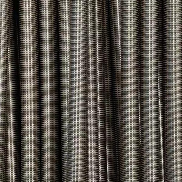
Low fin tubes feature externally welded fins on a base tube, increasing surface area by up to 3x compared to smooth tubes. Unlike high-fin tubes, their lower, spaced fins minimize airflow resistance while maximizing heat transfer. This design is ideal for applications requiring efficient cooling without pressure drop, such as oil refineries and HVAC condensers.
| Tube Type | Surface Area Increase | Pressure Drop | Fouling Resistance | Typical Applications |
|---|---|---|---|---|
| Smooth Tubes | Baseline (0%) | Low | Good | General purpose, clean fluids |
| Low Fin Tubes | 250-350% | Moderate | Good | HVAC, Refineries, Power Plants |
| High Fin Tubes | 500-800% | High | Poor | Gas-to-gas heat exchange |
| Integral Fin Tubes | 200-300% | Low-Moderate | Excellent | Corrosive environments |
Critical Dimensions for Maximum Thermal Efficiency
-
Base Tube Diameter
- Standard sizes: 1/2" to 4" (12.7 mm to 101.6 mm).
- Larger diameters increase surface area but require more installation space.
- Pro Tip: Pair with corrosion-resistant materials (e.g., stainless steel) for harsh environments.
-
Fin Height
- Range: 1–2 mm (0.04–0.08 inches).
- Taller fins boost heat transfer but risk fouling in dirty fluids.
-
Fin Pitch
- Optimal spacing: 2–4 mm (0.08–0.16 inches).
- Wider pitches reduce clogging in viscous fluids (e.g., crude oil).
-
Fin Thickness
- Standard: 0.2–0.5 mm (0.008–0.02 inches).
- Thicker fins improve durability but reduce thermal conductivity.
-
Tube Length
- Customizable from 1–20 meters based on system requirements.
| Base Tube OD (mm) | Fin Height (mm) | Fin Pitch (mm) | Surface Area Ratio | Heat Transfer Coefficient (W/m²·K) | Recommended Fluid |
|---|---|---|---|---|---|
| 15.88 | 1.0 | 1.5 | 2.8 | 2800-3200 | Refrigerants |
| 19.05 | 1.2 | 2.0 | 2.9 | 2600-3000 | Water/Glycol |
| 25.40 | 1.5 | 2.5 | 3.1 | 2400-2800 | Oil/Hydraulic Fluids |
| 31.75 | 1.6 | 3.0 | 3.2 | 2200-2600 | Process Chemicals |
| 50.80 | 1.8 | 3.5 | 3.4 | 2000-2400 | Steam/Condensate |
Why Dimensions Impact Thermal Efficiency
- Surface Area vs. Pressure Drop: Closer fin pitches increase surface area but raise airflow resistance. For gas-based systems (e.g., radiators), balance pitch with fan energy costs.
- Material Selection: Thinner fins made of copper or aluminum enhance conductivity but require anti-corrosion coatings for chemical processing.
- Case Study: A 2023 study by Thermal Engineering Journal showed 19% higher efficiency in low fin tubes (1.5 mm height, 3 mm pitch) vs. smooth tubes in refinery condensers.
Advantages
- Enhanced heat transfer efficiency (15-40% improvement over smooth tubes)
- Compact design saves space
- Lower material costs compared to high-fin tubes
- Good fouling resistance with proper fin spacing
- Wide range of material compatibility
Limitations
- Higher pressure drop than smooth tubes
- More difficult to clean than smooth tubes
- Limited effectiveness with highly viscous fluids
- Higher initial cost than smooth tubes
- Potential for fin damage during handling
Applications of Low Fin Tubes
- Oil & Gas: Crude oil cooling, LNG heat exchangers.
- Power Plants: Steam condenser tubes for turbines.
- HVAC: High-efficiency evaporators and condensers.
- Chemical Processing: Reactor cooling, distillation columns.
- Automotive: Lightweight radiators with 20% faster cooling (source: SAE International).
| Application | Recommended Material | Optimal Fin Height | Optimal Fin Pitch | Performance Improvement |
|---|---|---|---|---|
| HVAC Condensers | Copper | 1.2-1.5 mm | 1.8-2.2 mm | 25-35% |
| Refinery Heat Exchangers | Stainless Steel 316 | 1.5-1.8 mm | 2.5-3.5 mm | 18-25% |
| Power Plant Condensers | Admiralty Brass | 1.0-1.3 mm | 2.0-2.5 mm | 20-28% |
| Chemical Reactors | Hastelloy/Titanium | 1.2-1.6 mm | 2.2-2.8 mm | 22-30% |
| Automotive Radiators | Aluminum | 0.8-1.2 mm | 1.5-2.0 mm | 30-40% |
Low Fin Tubes for Heat Exchangers Performance
Based on industry data from 2020-2023, properly dimensioned low fin tubes can reduce heat exchanger size by 15-30% for the same thermal duty, leading to significant cost savings in material and installation.
Optimizing low fin tube dimensions is non-negotiable for engineers seeking peak thermal efficiency in heat exchangers. Prioritize fin height and pitch to reduce energy costs, minimize fouling, and extend equipment lifespan. For industry-specific guidance, consult manufacturers like Wolverine Tube or Hudson Products to tailor dimensions to your application.