


Industrial processing plants, power generation stations, and chemical refineries face continuous pressure to minimize water consumption while maintaining high thermal rejection efficiency. Traditional wet cooling towers discharge significant volumes of water through evaporation and drift, driving plant operators toward dry cooling architectures. At the center of this technological shift sits the Air-Cooled Condenser, a specialized dry-cooling system that utilizes forced or induced air streams across ACC units to condense turbine exhaust steam or process vapors without consuming liquid water resources.
Achieving optimal thermal performance within a dry cooling bay requires robust extended surface tubing. Because air possesses a relatively low volumetric heat capacity and thermal conductivity compared to water, bare metal tubes cannot achieve required duty cycles within practical physical footprints. Integrating high-performance finned tubes—such as high-frequency welded solid fins and Elliptical Brazed Finned Tubes—multiplies the external air-side surface area. This technical reference examines operational principles, core thermodynamic parameters, calculation frameworks, tube selection criteria, and structural trade-offs for modern Air-Cooled Condenser installations.
What Is an Air-Cooled Condenser?
An Air-Cooled Condenser is a direct dry cooling heat exchanger designed to condense low-pressure steam from a turbine exhaust duct or chemical vapor directly inside finned tube bundles, rejecting latent heat directly into ambient air. Unlike indirect dry cooling systems that rely on intermediate surface condensers and circulating water loops, a direct ACC routes steam from the turbine riser straight into overhead manifold headers feeding inclined A-frame bundle modules.
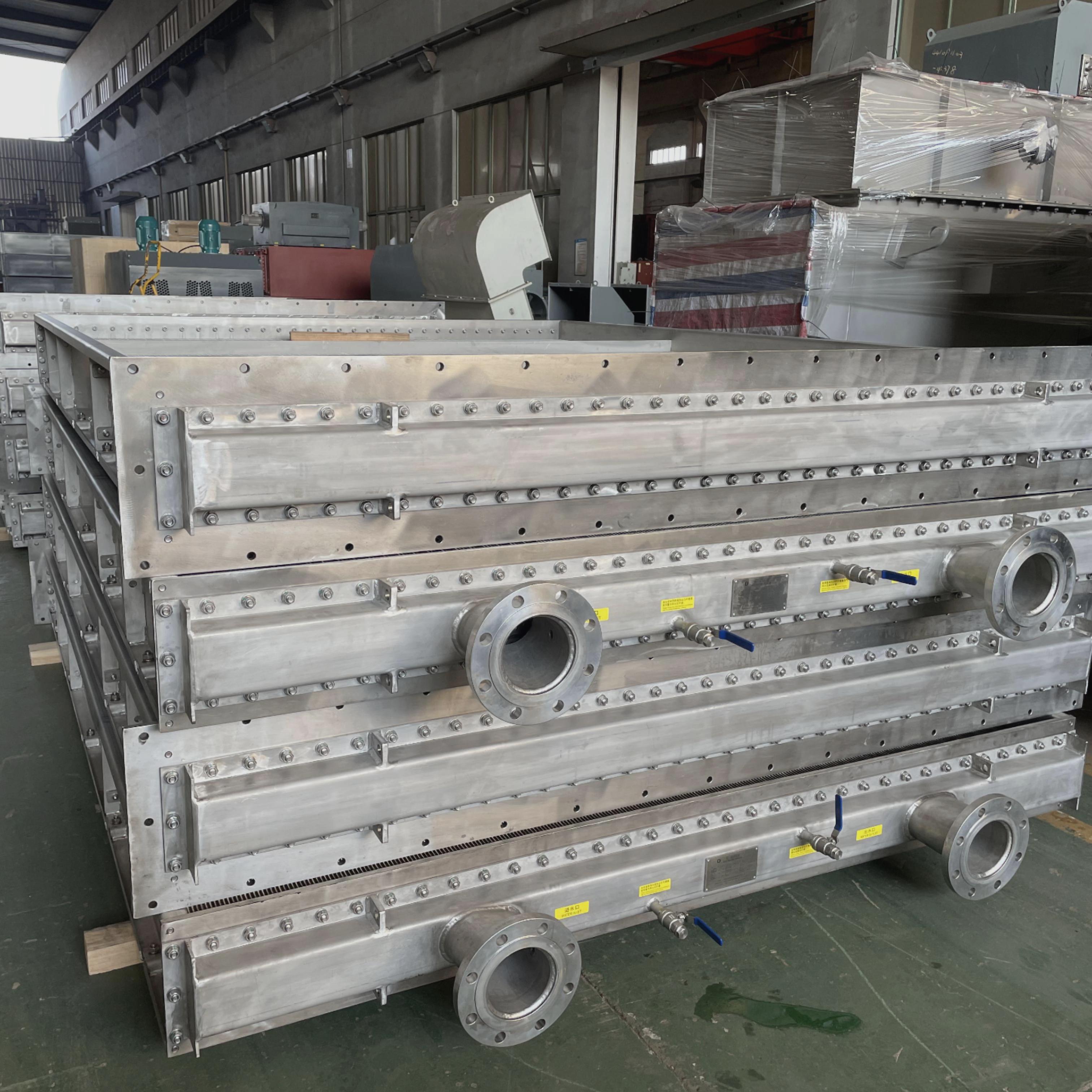
The operational workflow inside an Air-Cooled Condenser follows a continuous thermal sequence:
- Steam Delivery: Low-pressure turbine exhaust steam enters large overhead steam ducts and distributes evenly into individual condensation cells.
- Internal Condensation: Steam flows downward through the internal bore of the finned tubes. Massive axial fans drive ambient air upward across the exterior fin surface, drawing thermal energy through the tube wall via latent heat transfer.
- Condensate Recovery: Liquid condensate drains by gravity into bottom headers and returns to the boiler feed water system, while non-condensable gases are evacuated through dedicated vacuum extraction ports.
What Is Overall Heat Transfer Coefficient (U)?
The overall heat transfer coefficient (U) is a primary thermal metric measuring the total rate of heat transfer per unit surface area per degree of temperature difference between the condensing steam and cooling air. Expressed in W/(m²·K), the typical range for ACC air-side finned bundles is 25 to 45 W/(m²·K) based on total external surface area, with final figures subject to project specification, engineer verification, and manufacturer testing.
The overall heat transfer coefficient is influenced heavily by the dominant thermal resistance on the air side. Because external air convection resistance is much higher than internal steam condensation resistance, expanding the external surface area via finned tubes is mandatory. Higher U values indicate superior thermal performance, allowing for a more compact bundle array and reduced fan power consumption.
What Is Initial Temperature Difference (ITD)?
Initial Temperature Difference (ITD) is defined as the temperature difference between the entering saturated steam temperature and the entering ambient dry-bulb air temperature, expressed in Kelvin (K) or degrees Celsius (°C). The typical range for industrial ACC design is 15 K to 30 K under rated operating conditions.
ITD dictates the thermodynamic driving force of the system. Lower ITD values improve steam turbine efficiency by maintaining lower backpressure, but they require exponentially larger heat transfer surface areas and increased structural steel investment. Conversely, higher ITD reduces capital equipment size at the expense of elevated turbine exhaust pressure and reduced net power output.
What Is Air-Side Pressure Drop (ΔP_air)?
Air-side pressure drop (ΔP_air) measures the static pressure resistance encountered by ambient air as it is forced or induced across the finned tube bundle arrays, expressed in Pascals (Pa) or inches of water column (in. WC). The typical range per bundle row is 30 to 120 Pa, depending on fin pitch and air face velocity.
Managing air-side pressure drop is critical for optimizing auxiliary fan power. Excessive pressure drop increases electrical power consumption for fan motors, while overly sparse fin configurations sacrifice necessary heat transfer surface area.
How Is Overall Heat Transfer Coefficient Calculated?
The thermal heat duty (Q) of an Air-Cooled Condenser module is governed by the fundamental heat exchanger equation:
Q = U × A_ext × ΔT_lm
Where:
- Q = Total thermal heat duty (W)
- U = Overall heat transfer coefficient based on external area (W/(m²·K))
- A_ext = Total external extended surface area of the finned tubes (m²)
- ΔT_lm = Logarithmic Mean Temperature Difference (K or °C)
Because extended fins experience thermal efficiency drop along their height, the effective overall thermal resistance is calculated by summing individual resistances across the wall, internal fluid, fouling layers, and external fin array:
1 / U = (1 / h_int) × (A_ext / A_int) + R_wall + R_foul + 1 / (η_o × h_ext)
Where:
- h_int = Internal steam condensation film heat transfer coefficient (W/(m²·K)), typical range 5000 to 10000 W/(m²·K)
- A_ext / A_int = Ratio of external extended area to internal bare tube area, typical range 12 to 25
- R_wall = Convective wall thermal resistance of base tube (m²·K/W)
- R_foul = Internal and external fouling factor (m²·K/W), typical range 0.0001 to 0.0002 m²·K/W
- h_ext = External air-side convective heat transfer coefficient (W/(m²·K)), typical range 30 to 80 W/(m²·K)
- η_o = Overall surface efficiency of the finned array, typical range 0.80 to 0.95
How Does Overall Heat Transfer Coefficient Affect Performance?
The overall heat transfer coefficient directly dictates how efficiently thermal energy passes from the condensing steam into the cooling air stream. A higher U value ensures that a greater quantity of steam is condensed per unit of time within a fixed physical surface area. If the U value degrades due to external fouling or internal non-condensable gas blanketing, steam condensation slows down, causing turbine backpressure to spike, cycle efficiency to drop, and total plant electrical output to decline.
Design Trade-offs in ACC Finned Tube Selection
Engineers must evaluate several interconnected design variables when specifying finned tubes for industrial Air-Cooled Condenser units:
1. Fin Density (Fins Per Inch / FPI) vs. Air-Side Pressure Drop
Increasing fin density from 275 fins/m (7 FPI) to 394 fins/m (10 FPI) expands the total external heat transfer area, reducing the required physical footprint. However, higher fin density increases air-side pressure drop (ΔP_air) and fan power requirements, and accelerates performance degradation from airborne dust accumulation in arid environments.
2. Ambient Temperature Swings vs. Turbine Backpressure
Air-Cooled Condenser systems operate under variable seasonal ambient conditions. Peak summer temperatures narrow the Initial Temperature Difference, elevating turbine exhaust backpressure. Thermal design teams must balance capital expenditure for larger plot areas and bundle counts against long-term plant efficiency losses during hot weather peaks.
3. Tube Geometry: Round High-Frequency Welded vs. Elliptical Tubes
Multi-row round finned tubes offer economical manufacturing costs but suffer from air preheating across trailing rows. Single-row elliptical tube designs optimize aerodynamics and eliminate multi-row preheating effects, though requiring higher initial investment.
Technical Specifications, Materials, and Standards
Air-Cooled Condenser finned tubes must withstand vacuum pressure differentials, mechanical vibration from axial fans, and atmospheric exposure. Specifications below represent typical ranges and must be confirmed against final project engineering requirements.
| Parameter / Specification Dimension | Typical Range / Technical Limit | Applicable Standard / Material Class |
|---|---|---|
| Base Tube Outer Diameter (OD) | 25.4 mm to 50.8 mm (Round) / 100 mm x 20 mm (Elliptical) | ASTM A106 Gr. B / ASTM A214 |
| Fin Height | 10 mm to 25 mm | Aluminum 1060 / 1100 or Carbon Steel |
| Fin Density (FPI) | 236 to 394 fins per meter (6 to 10 FPI) | Per project specification and dust loading |
| Base Tube Wall Thickness | 2.0 mm to 4.0 mm (Full vacuum rated) | ASME BPVC Section VIII Division 1 |
| Design Pressure / Temperature | Full vacuum to 1.5 MPa / Up to 350°C | API 661 / ISO 13706 |
Application Industries
Direct Air-Cooled Condenser systems are deployed globally across heavy industrial sectors requiring efficient heat rejection without water dependency:
- Thermal and Combined-Cycle Power Plants: Coal, gas turbine (CCGT), and biomass electricity generation facilities located in water-scarce regions.
- Concentrated Solar Power (CSP): Solar tower and parabolic trough installations operating in arid desert locations.
- Petrochemical Refineries: Hydrocarbon fractionator overhead condensers and steam turbine drive exhaust systems.
- Waste-to-Energy Plants: Municipal solid waste combustion complexes requiring reliable dry condensation loops.
- Geothermal Energy Stations: Binary cycle and steam power production units situated in ecologically protected zones.
Selection Guide for Procurement and Engineering Teams
Specifying finned tubes for new construction or ACC retubing projects requires systematic evaluation of site conditions:
- Assess Environmental Particulate Levels: Evaluate local wind rose data, sandstorms, or agricultural dust to select appropriate fin spacing and avoid rapid fouling.
- Determine Metallurgical Compatibility: Choose stainless steel base tubes or hot-dip galvanized finishes when operating in corrosive coastal or industrial atmospheres.
- Verify Structural Vacuum Rigidity: Ensure base tube wall thicknesses satisfy full vacuum collapse calculations under peak operating steam temperatures.
- Evaluate Maintainability: Specify robust fin attachment methods—such as high-frequency resistance welding or bimetallic extrusion—that endure high-pressure water washing without fin distortion.
Quality Control and Testing Protocols
Manufacturing finned tubes for high-vacuum Air-Cooled Condenser bundles requires strict quality inspection standards:
- Fin Bond Strength Test: Mechanical pull-off testing to verify intimate contact resistance and prevent thermal barrier formation.
- Hydrostatic Testing: Internal pressure testing of base tubes per ASTM guidelines prior to fin application.
- Pneumatic and Vacuum Leak Testing: Helium mass spectrometer testing on assembled bundle headers to guarantee zero air ingress.
- Dimensional and Straightness Inspection: Verification of wall thickness, fin pitch consistency, and tube straightness tolerances within 1.0 mm per meter.
Packaging and Shipping Requirements
Finned tubes feature delicate extended surfaces susceptible to impact damage during international transport. Standard export preparation includes:
- Heavy-Duty Steel Transport Craters: Tubes secured inside rigid structural timber or steel transport frames fitted with custom HDPE bundle spacers to prevent fin contact.
- Protective End Closures: Plastic bevel caps installed on plain tube ends to protect weld preps from moisture and foreign debris.
- Vapor Corrosion Inhibitors: Industrial VCI wrapping and moisture barrier foils applied to safeguard against marine atmosphere oxidation during ocean transit.
Frequently Asked Questions (FAQ)
1. What is an Air-Cooled Condenser?
An Air-Cooled Condenser is an industrial dry cooling system that condenses turbine exhaust steam or process vapors directly inside finned tube bundles using ambient air streams, eliminating the need for cooling tower water.
2. What is Overall Heat Transfer Coefficient?
Overall Heat Transfer Coefficient (U) measures the total thermal transfer rate per unit surface area per degree of temperature difference, typically ranging from 25 to 45 W/(m²·K) for air-side ACC finned bundles.
3. What is Initial Temperature Difference?
Initial Temperature Difference (ITD) is the temperature difference between entering saturated steam and entering ambient dry-bulb air, with a typical range of 15 K to 30 K in ACC design.
4. What is Air-Side Pressure Drop?
Air-Side Pressure Drop (ΔP_air) is the static pressure resistance encountered by cooling air moving across finned tube bundle rows, with a typical range of 30 to 120 Pa per row.
5. How is Overall Heat Transfer Coefficient calculated?
It is calculated using the total heat duty equation Q = U × A_ext × ΔT_lm, factoring in internal condensation coefficients, wall resistance, fouling factors, and external air-side convective resistance.
6. How does Overall Heat Transfer Coefficient affect performance?
A higher U value accelerates steam condensation within a given physical area, preventing turbine backpressure spikes and maintaining optimal power generation efficiency.
7. How to design when considering trade-offs between fin density and pressure drop?
Engineers balance higher fin density (FPI) for compact footprints against increased air-side pressure drop (ΔP_air) and fan power consumption, adjusting spacing based on site dust levels.
8. Why choose high-frequency welded or elliptical finned tubes for ACC systems?
They provide superior mechanical strength, robust thermal bonding, resistance to high-pressure cleaning, and optimized air-side aerodynamic performance under severe industrial duty cycles.
Optimize Your Dry Cooling System with High-Performance Finned Tubes
Looking for reliable high-frequency welded or elliptical finned tubes for your next Air-Cooled Condenser project, retrofitting, or retubing program? Lordfintube delivers precision-engineered heat transfer solutions manufactured to strict international pressure vessel standards.
Request a Quote