

Enhanced Heat Transfer Tube for Heat Exchanger
Enhanced heat transfer tubes represent advanced engineering solutions designed to significantly improve thermal efficiency in heat exchangers, boilers, and various chemical processing equipment. As industry experts with decades of experience in heat exchanger design and manufacturing, we provide this comprehensive technical guide to help engineers and procurement specialists understand the capabilities, applications, and selection criteria for different enhanced heat transfer tube technologies.
Fundamentals of Heat Transfer Enhancement
Enhanced heat transfer tubes are specialized thermal elements engineered to intensify heat exchange between fluids flowing inside and outside the tube. The enhancement mechanisms are broadly categorized based on the phase condition of the working fluid:
Non-Phase-Change Enhancement
For single-phase fluids where no phase transition occurs, enhancement techniques focus on disrupting boundary layers and promoting turbulence:
- Spirally grooved tubes
- Corrugated tubes
- Twisted tubes
- Internal inserts (twisted tapes, wire coils)
- Pulsating flow induction
Phase-Change Enhancement
For boiling, evaporation, or condensation processes, enhancement focuses on nucleation sites and phase separation:
- Single longitudinal fin tubes
- Low-finned tubes
- Serrated finned tubes
- Radial finned tubes
- Surface porous tubes
- Double longitudinal fin tubes
Expert Insight: The selection between non-phase-change and phase-change enhancement technologies depends on the specific application, fluid properties, operating temperatures, and pressure constraints. In chemical processing applications, enhanced heat transfer tubes can reduce heat exchanger size by up to 40% while maintaining the same thermal duty.
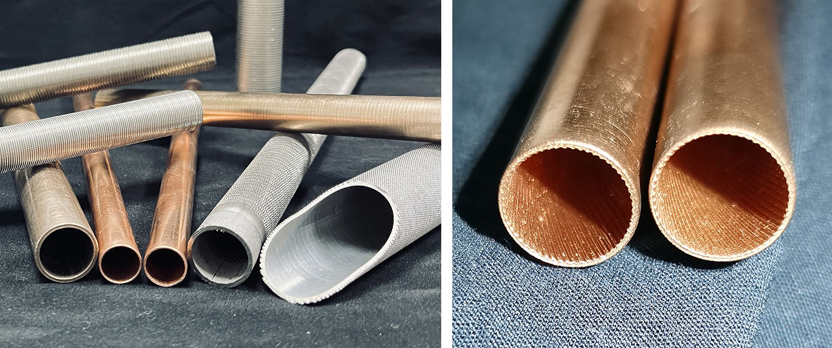
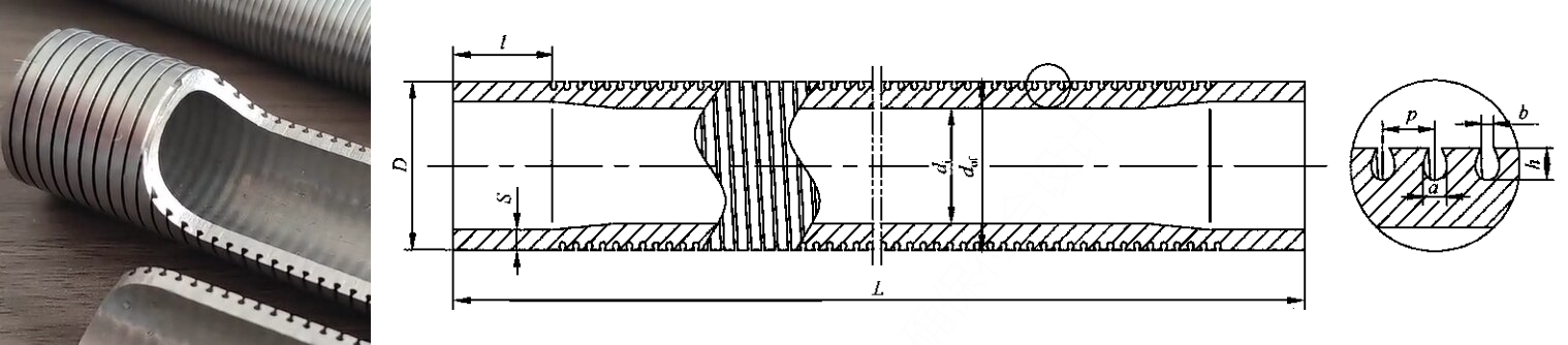
1. Integral Low-Finned Tube
Low-finned tubes are manufactured through a precision mechanical rolling process that forms fins of specific height, spacing, and thickness directly from the base tube material. This creates a monolithic structure where fins and tube are a single piece of metal, eliminating thermal resistance at the interface.
Technical Parameters
| Parameter | Specification |
|---|---|
| Manufacturing Process | Rolled from integral seamless tube |
| Materials | Stainless steel, Titanium alloy, Nickel alloy |
| Fin Height | 0.8mm - 1.5mm (standard) |
| Fin Density | 11-40 fins per inch (FPI) |
Configuration Types
- External low fins + Internal smooth bore: Ideal for shell-side enhancement with clean tube-side fluids
- External low fins + Internal spiral rifling: Dual enhancement for challenging applications with fouling potential
Industrial Applications
Integral low-finned tubes are extensively used in hydrocarbon processing, power generation, and refrigeration systems. Their robust construction makes them suitable for high-pressure applications up to 100 bar, with temperature resistance ranging from cryogenic conditions to 800°F (427°C) depending on the base material.
2. T-fin Low Finned Tube / Gewa-T Tube / T-Shaped Grooved Tube
The T-fin tube features a unique spiral fin with a T-shaped cross-section created through specialized rolling techniques. This innovative design creates a sophisticated boiling enhancement mechanism particularly effective for refrigerants and light hydrocarbons.
Enhanced Boiling Mechanism
The T-fin design creates a distinctive gap geometry between adjacent fins - wider at the base and narrower at the top. This configuration initiates a sophisticated boiling cycle:
- Vapor nucleation begins at the wider bottom section of the gaps between fins
- Rapid bubble expansion fills the entire bottom cavity due to omnidirectional heating
- Increasing vapor pressure forces bubble ejection through the narrow top slit
- This jetting action creates local negative pressure, drawing in cooler liquid
- The cycle repeats, establishing continuous high-efficiency boiling
Performance Advantages
- Exceptional heat transfer efficiency: Up to 3 times higher than plain tubes
- Space optimization: Reduces required heat transfer area by ≥30%
- Fouling resistance: Self-cleaning action minimizes deposit accumulation
- Lower approach temperatures: Enables closer temperature approaches in evaporation
Engineering Note: T-fin tubes demonstrate particular effectiveness in flooded evaporators and kettle reboilers handling low-temperature differential applications. The enhanced nucleation characteristics reduce wall superheat requirements by 40-60% compared to plain surfaces.
3. Sintered Surface Porous Tube (High-Flux Tube)
High-Flux tubes utilize powder sintering technology to create a porous metal layer with microscopic vapor nucleation sites on the tube surface. This advanced surface engineering produces heat transfer performance up to 15.6 times greater than conventional plain tubes, representing the pinnacle of boiling enhancement technology.
Technical Specifications
| Parameter | Specification |
|---|---|
| Base Tube Materials | Carbon steel, Alloy steel, Stainless steel, Copper & Copper alloys |
| Sintered Powder Types | Fe-based alloy, Cu-based alloy, Cu-Ni alloy |
| Tube Configurations | Straight tube, U-Bent |
| Tube Dimensions | OD: 19mm - 32mm; Length: 3 - 12m (+10mm tolerance) |
| Porous Layer Properties | Thickness: 0.1mm - 0.3mm; Porosity: 30% - 70% |
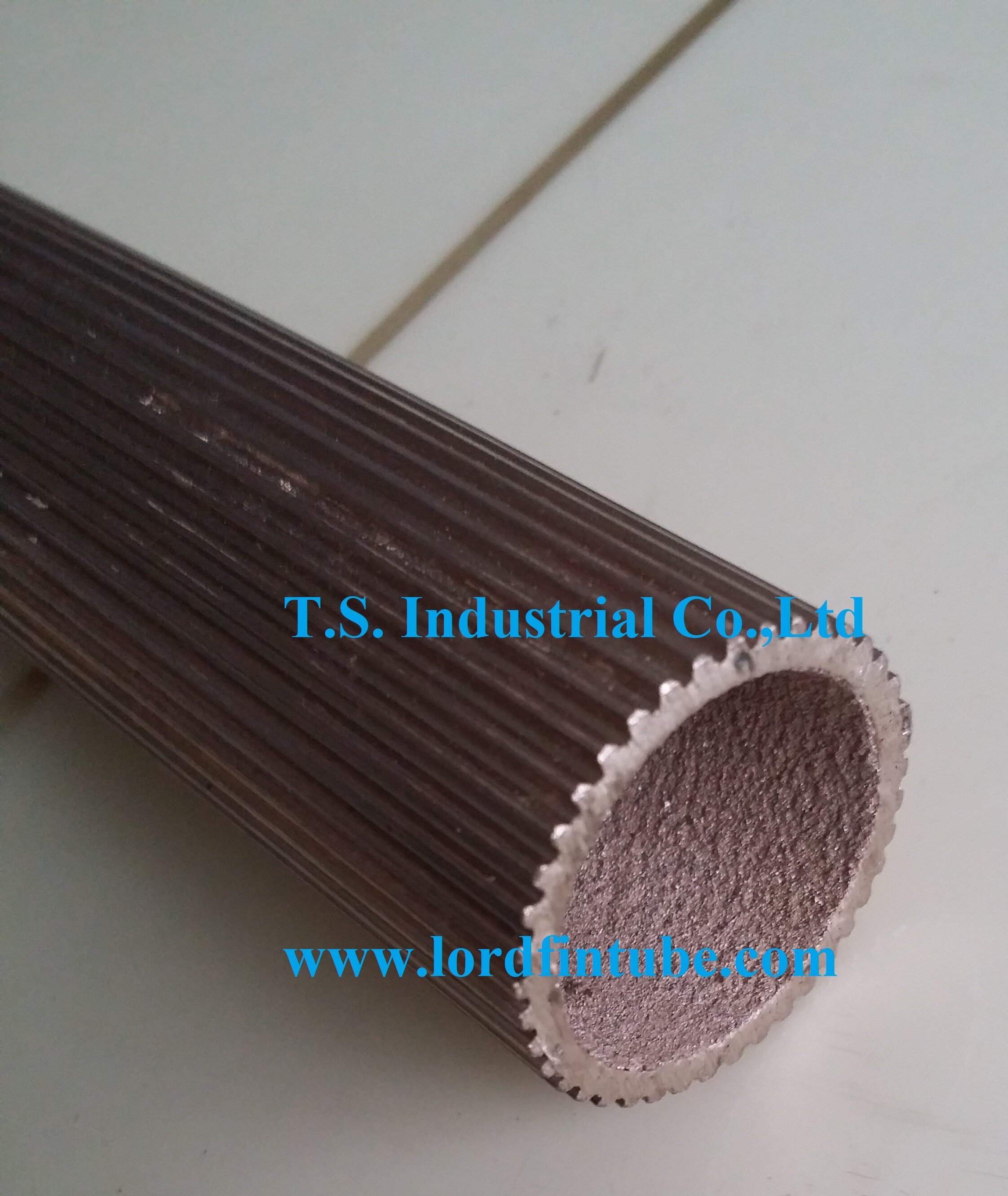
Product Variants
- Externally Sintered Porous Layer: Optimized for shell-side boiling applications
- Internally Sintered Porous Layer: Enhanced tube-side boiling performance
- External Longitudinal Grooves + Internally Sintered Porous Layer: Combined enhancement for challenging fluids
- Externally Sintered Porous Layer + Internal Low Fins: Maximum performance dual enhancement
Critical Applications
High-Flux tubes deliver exceptional performance in LNG heat exchangers, ethylene plant chillers, and refrigeration systems where minimal temperature approaches are critical. The porous structure provides approximately 10-100 times more active nucleation sites per unit area compared to plain surfaces, enabling efficient operation with temperature differences as low as 1-2°C.
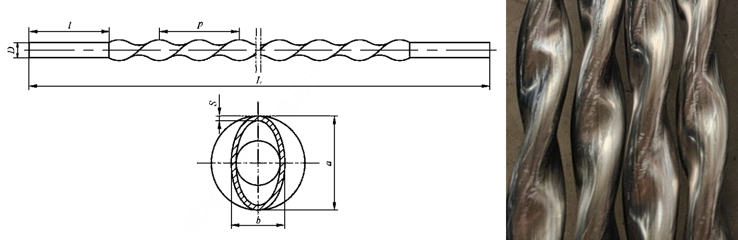
4. Twisted Tube Heat Exchanger Technology
Twisted tubes feature an elliptical cross-section throughout their heat transfer length, created by flattening and twisting round base tubes. This unique geometry induces spiral flow patterns in both tube-side and shell-side fluids simultaneously, creating synergistic turbulence enhancement.
Material Compatibility
Available in stainless steel, carbon steel, and copper alloys to match specific corrosion and temperature requirements.
Performance Benefits
- Reduced pressure drop: Optimized flow paths decrease energy consumption
- Enhanced fouling resistance: Continuous surface variation minimizes deposit attachment
- Superior heat transfer efficiency: Dual-side enhancement without inserts or complex geometries
- Vibration resistance: Structural rigidity reduces flow-induced vibration issues
Twisted tubes provide exceptional performance where tube-side resistance controls heat transfer rates, applicable across non-phase-change, boiling, and condensation applications. The elliptical profile creates natural support points between adjacent tubes, eliminating the need for baffles in many configurations and reducing shell-side pressure drop by up to 50%.
Design Advantage: The twisted tubes unique geometry creates a self-supporting bundle that eliminates traditional baffles, reducing dead zones and mitigating vibration concerns while improving shell-side heat transfer coefficients by 30-40% compared to conventional segmented baffle designs.
5. Stainless Steel Corrugated Tube
Corrugated tubes are manufactured by applying specialized forming processes to standard heat transfer tubes, creating consistent concave-convex patterns on both inner and outer surfaces. This design provides simultaneous enhancement for internal and external heat transfer through boundary layer disruption.
Operational Advantages
- Enhanced heat transfer coefficients: 2-3 times higher than plain tubes
- Robust pressure containment: Suitable for low to medium pressure applications
- Superior corrosion resistance: Long service life in aggressive environments
- Thermal stress accommodation: Withstands significant temperature differentials
- Fouling mitigation: Surface turbulence minimizes deposit accumulation
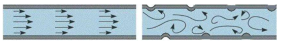
Performance Comparison
The alternating peaks and valleys in corrugated tubes create continuous flow direction changes that generate significant turbulence. This ensures all fluid elements interact with the tube wall, effectively eliminating the thermal boundary layer limitations present in smooth tubes. The overall heat transfer coefficient typically increases by 2 to 3 times, with some operational scenarios achieving up to 5 times improvement.
Industrial Implementation
Corrugated tubes excel in chemical processing heat exchangers, HVAC systems, and food processing applications where thermal efficiency and cleanability are paramount. The enhanced performance allows for more compact exchanger designs or increased capacity in existing units. The mechanical strength of the corrugated profile also provides improved resistance to operational stress and thermal cycling compared to plain tubes of equivalent thickness.
Selection for Enhanced Heat Transfer Tubes
Choosing the appropriate enhanced heat transfer tube technology requires careful consideration of multiple factors:
Application-Specific Recommendations
- High-fouling services: Corrugated tubes or twisted tubes with their self-cleaning action
- Boiling applications: T-fin tubes or High-Flux tubes for superior nucleation
- Condensation duties: Low-finned tubes with optimized fin geometry
- Viscous fluids: Twisted tubes for enhanced mixing at lower Reynolds numbers
- High-pressure services: Integral low-finned tubes for structural integrity
- Cryogenic applications: High-Flux tubes for minimal temperature approaches