


Finned tubes are bare tubes modified to extend heat‑transfer surface area. They are widely used for gas‑to‑gas and gas‑to‑liquid waste‑heat recovery across industrial processes. Multiple fin configurations are available: spiral, longitudinal, serrated, and H‑type. Common manufacturing methods include high‑frequency welding, laser welding, extrusion, and mechanical wrap‑on. Material options cover carbon steel, stainless steel, ND steel, and copper‑aluminium composites. With so many combinations available, proper product selection requires careful evaluation.
Most buyers compare quotations based on three dimensional parameters: fin height, fin pitch, and base‑tube outer diameter. While these dimensions influence thermal performance, they do not define the actual service life of a finned‑tube heat exchanger. Operating conditions are the primary factor governing long‑term equipment reliability.
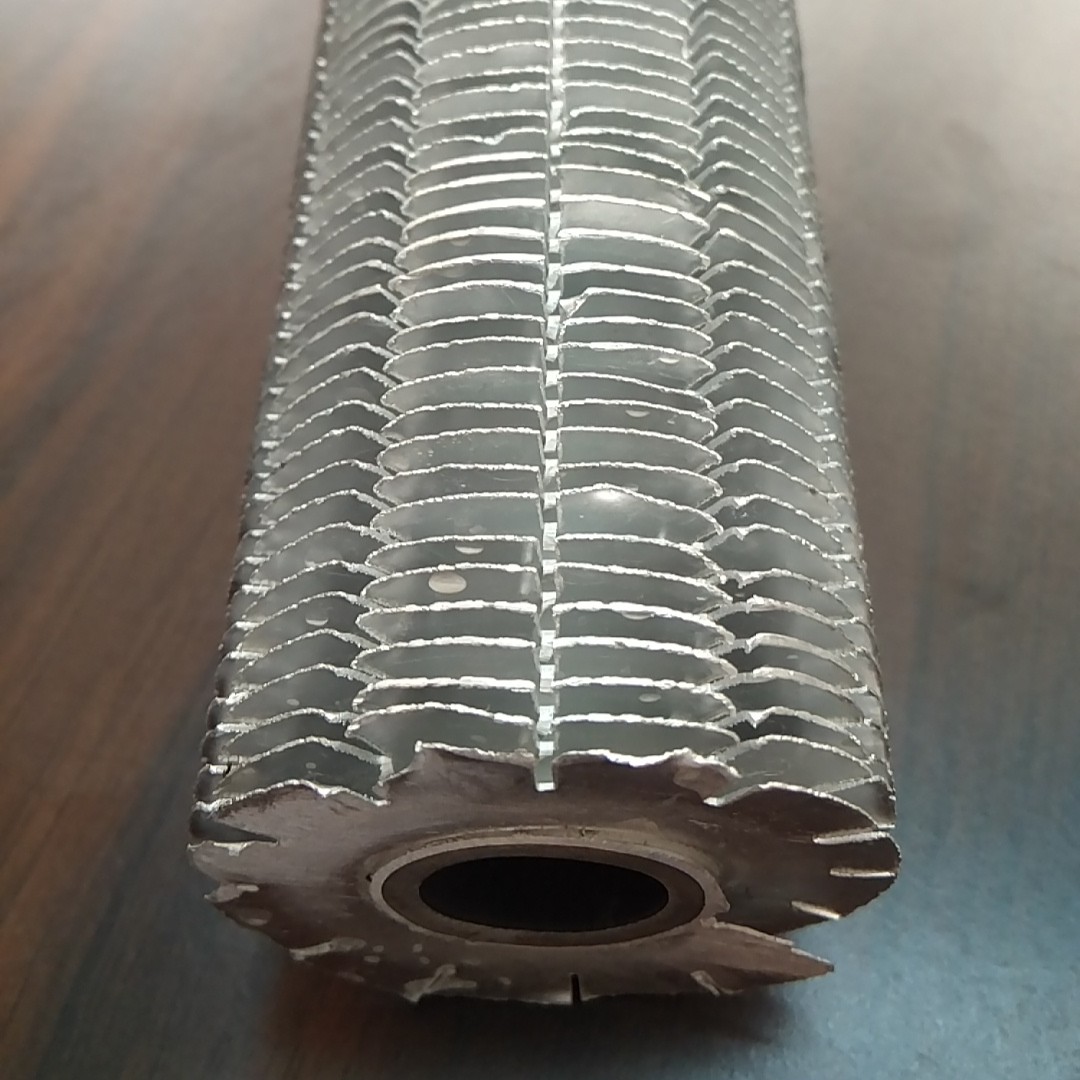
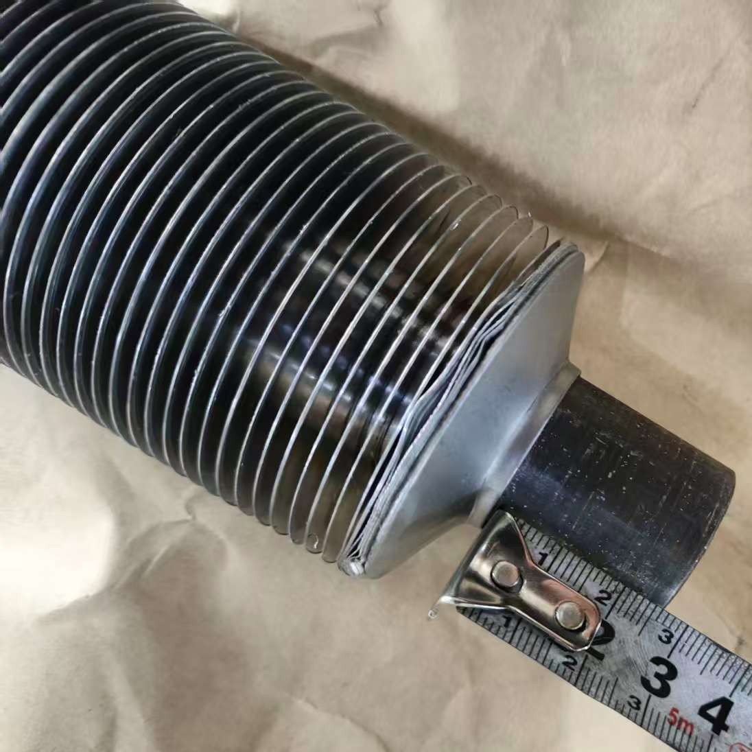
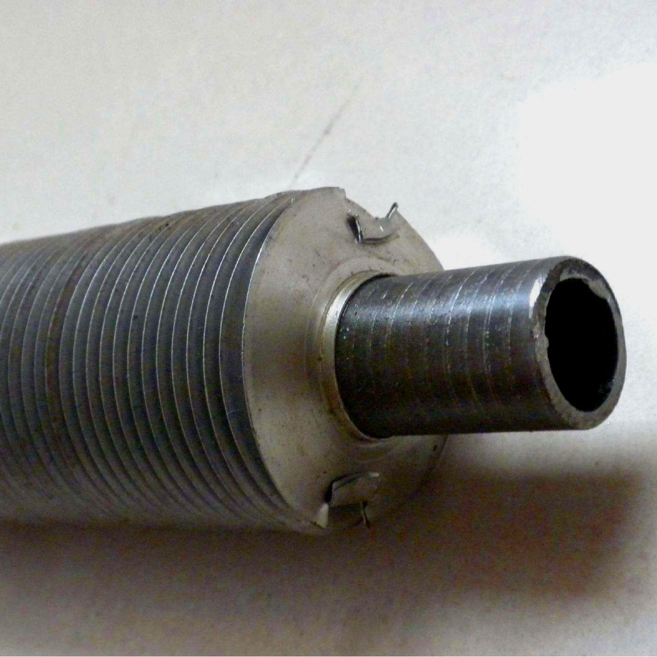
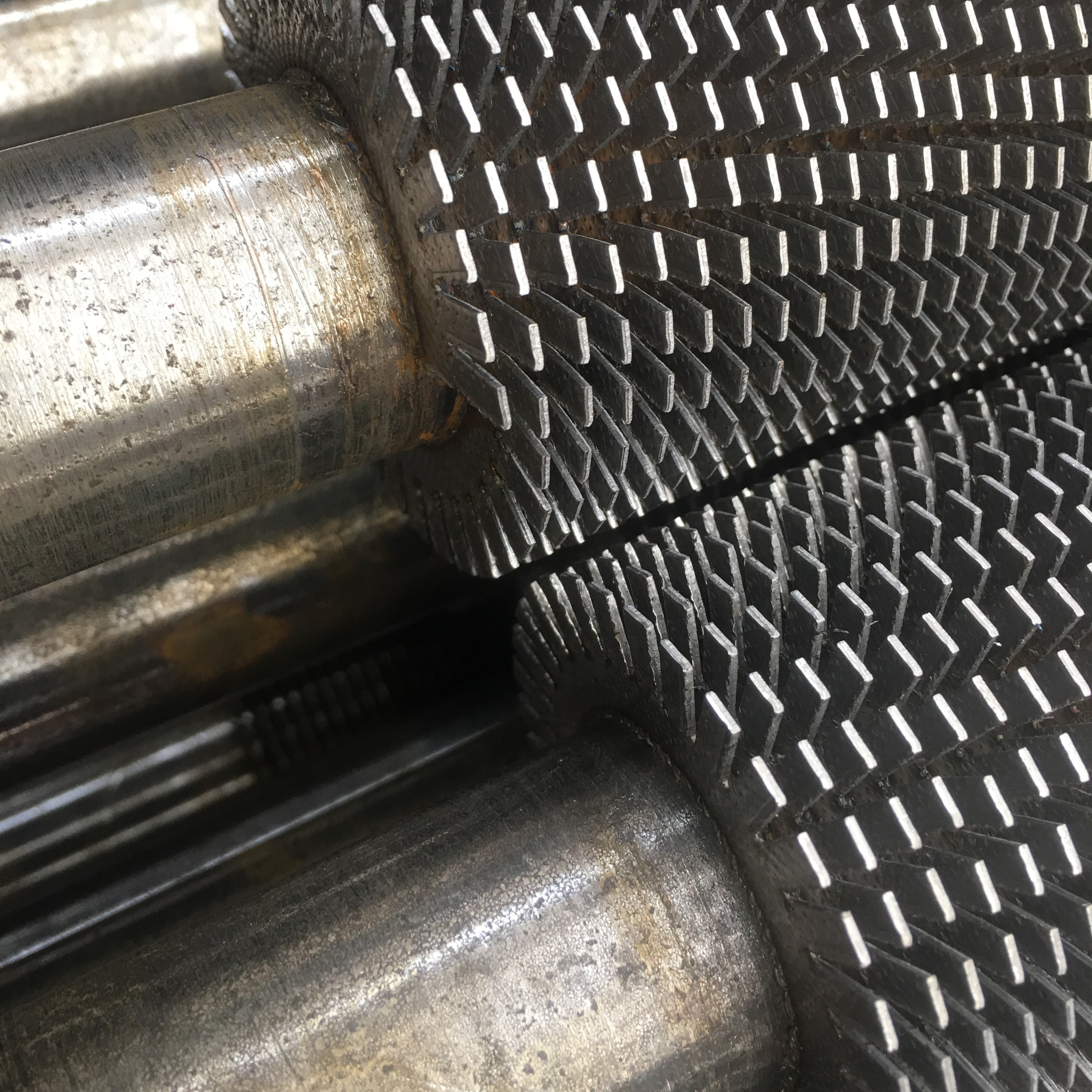
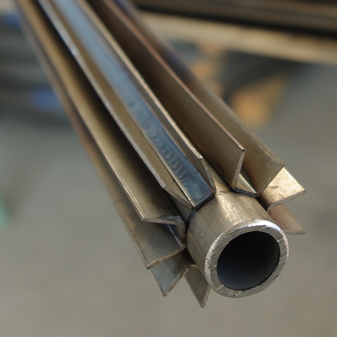
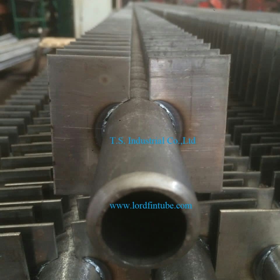
Among the configurations shown above, Extruded Finned Tube offers very low thermal resistance and good oxidation resistance, making it suitable for clean, low‑temperature duties. Spiral Wound Finned Tube is frequently specified for small‑to‑medium scale projects due to its flexible manufacturing and competitive cost structure. For low‑temperature heating applications with budget constraints and short delivery schedules, L Type Finned Tube remains a practical alternative. In dusty, fouling‑prone medium‑to‑low temperature flue gas streams, the anti‑deposition characteristics of Longitudinal Finned Tube often provide more reliable long‑term performance than a marginal improvement in the bare heat transfer coefficient.
Base tube material governs corrosion resistance and pressure integrity
A common oversight is to evaluate fin geometry while neglecting base tube compatibility with the process fluids. The base tube serves as the primary pressure boundary. Its material must withstand the combined effects of temperature, pressure, and chemical attack from both the tube-side and shell-side media.
Flue gas containing sulphur, chlorine, or moisture at dew‑point conditions demands an upgrade from carbon steel to stainless steel or duplex alloys. In such cases, the selection sequence changes fundamentally: first specify the base tube metallurgy, then identify a finning process that is metallurgically compatible and thermally adequate.
For air coolers and air preheaters, ASTM A179 or A192 low‑carbon seamless tubes are commonly used. Power‑plant economisers and superheaters typically start from A210 or T11/T22 alloy grades. A mismatch between base tube material and the corrosive environment cannot be compensated for by any fin design or by increasing fin density.
Comparison of common finned tube configurations
Once the base tube material is fixed, the fin geometry and attachment method can be evaluated.
High‑Frequency Welded Serrated (Open‑Tooth)
Steel strip is spirally wound and welded at high frequency, with the fin edge notched to create serrations. The notches enhance turbulence and reduce dust bridging. The metallurgical bond provides strong adhesion and resistance to thermal cycling.
Temperature limits: carbon steel up to 300°C; stainless steel up to 420°C.
Typical services: combined‑cycle HRSGs, drying lines.
Q235B for clean fuel gas ND steel for sulphur dew‑point Stainless for humid/aggressive corrosionH‑Type (Paired Fin)
Fins are welded in opposing pairs on both sides of the tube, forming an H-shaped cross‑section. The geometry promotes cross‑flow turbulence and reduces ash accumulation. It is specifically engineered for high‑ash, high‑erosion flue gas streams.
Common tube ODs: Φ32, Φ38, Φ42.
Typical services: coal‑fired boilers, rotary kiln exhaust.
Single‑H / Double‑H variants Optimum at 9mm pitch / 1.2mm fin thicknessLongitudinal Finned Tube
Fins are aligned parallel to the tube axis. The heat transfer coefficient is moderately lower than spiral designs, but flow resistance and metal consumption are reduced. The longitudinal arrangement suppresses the wake region and minimises particle deposition.
Key advantage: resistance to fouling and scaling.
Typical services: dusty medium‑low temperature flue gas.
Niche application, high anti‑fouling valueExtruded Finned Tube (Bi‑Metallic)
An aluminium sleeve is extruded over a carbon steel base tube, forming integral fins with no interfacial gap. Thermal resistance is extremely low. The assembly is lightweight and oxidation‑resistant, with good durability in outdoor and salt‑laden environments.
Maximum continuous temperature: 260°C.
Typical services: HVAC coils, fresh‑air heaters, low‑grade recovery.
Not for use above 260°C or high‑sulphur gasL‑Type Wrap‑On
An L‑shaped aluminium strip is mechanically wrapped around the base tube without welding. Manufacturing cost and lead time are low. However, thermal cycling and vibration can loosen the fins over time, limiting service life in demanding conditions.
Typical services: small air‑conditioning coils, low‑temperature hot‑water heating.
Not recommended for continuous industrial processesSpiral Wound (Wrap‑On)
Aluminium or copper strip is helically wound onto the base tube under mechanical tension. No welding is involved. Cost and delivery times are attractive, but the mechanical bond can degrade under thermal cycling and vibration.
Typical services: small A/C coils, intermittent low‑temperature heating.
Suitable only for non‑continuous dutyKey dimensional and operational parameters
| Parameter | Clean low‑temp flue gas | Moderate dust flue gas | High‑dust / high‑wear kiln gas | High‑temperature superheater zone |
|---|---|---|---|---|
| Fin ratio | 8–12 (maximise area) | 5–8 (balance performance and fouling margin) | 3–5 (wider pitch to reduce plugging and erosion) | Keep low to avoid fin overheating |
| Fin pitch | 2–3 mm (dense) | 4–6 mm | 8–12 mm (include cleaning access) | Set according to temperature gradient |
| Fin height | Can be higher (boost gas‑side coefficient) | Moderate | Lower (reduce root erosion) | Lower |
| Fin thickness | 1.2–1.5 mm | 1.2–1.5 mm | ≥2 mm on leading face | 1.5–2.0 mm |
Material selection reference
Cost‑effective option
Stainless base tube + compatible fins
Lowest initial cost with carbon steel fins
Heat‑resistant alloy base; fins in 304 or 321
Low‑carbon seamless grades
Alloy tube starting points
Systematic selection criteria for finned tube heat exchangers
A well‑defined finned tube specification requires a step‑by‑step evaluation of the process conditions. Begin by documenting the tube‑side and shell‑side media, operating temperature and pressure ranges, and the concentration of corrosive species such as sulphur, chlorine, or water vapour.
Next, verify that the base tube material provides adequate corrosion allowance and creep‑rupture strength for the expected service life. After the base tube is determined, select a fin geometry that balances heat transfer enhancement with acceptable fouling propensity and pressure drop.
Finally, evaluate cleaning access, installation clearances, and tube‑bundle support arrangements. Plain (bare) tubes remain a robust alternative in high‑temperature, severely corrosive, or heavily fouling services where finned tubes would be prone to rapid degradation.
Spiral‑finned tubes perform well in clean medium‑low temperature flue gas. H‑type finned tubes are the preferred choice for high‑ash, high‑erosion environments. The selection must be validated against actual field data or pilot‑scale tests whenever possible.
Proper finned tube selection requires a balanced evaluation of thermal performance, mechanical strength, fouling characteristics, and life‑cycle cost. Relying on incomplete process data or prioritising a single parameter such as fin density often compromises long‑term reliability and increases maintenance expenditure. Engineering decisions should be guided by verified thermal and mechanical data, not by industry fashion or isolated benchmark comparisons.