


Fixed Tube Sheet Heat Exchanger
The fixed tube‑sheet heat exchanger is one of the most classic and widely‑used types among shell‑and‑tube heat exchangers. It undertakes the core task of heat transfer between hot and cold fluids in industries such as petroleum, chemical engineering, pharmaceutical manufacturing, food processing and power generation, serving as an indispensable energy‑saving device in industrial production. It plays a vital role in various scenarios, ranging from reactor cooling systems in chemical plants and waste‑heat recovery units in power stations, to sterilization equipment for food processing.
1. What is a “Fixed Tube‑Sheet”?
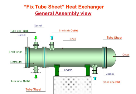
The defining feature of a fixed tube‑sheet heat exchanger lies in its “fixed” configuration. Its two tube‑sheets are directly welded to the shell, while both ends of the tube bundle are fastened to the tube‑sheets by welding or tube rolling. As a result, the tube bundle, shell and tube‑sheets form a rigid integrated assembly with no relative movement between components.
In terms of construction, a fixed tube‑sheet heat exchanger mainly consists of shell, tube‑sheets, tube bundle, and heads (channel boxes). Inside the cylindrical shell, parallel heat‑transfer tubes are fixed at both ends onto the tube‑sheets, which are in turn welded directly to the shell. The channel boxes are bolted to flanges on both ends of the shell, forming inlet and outlet passages for tube‑side fluid. Baffles (also known as support plates) are fitted on the shell‑side. They force shell‑side fluid to flow across the tube bundle, enhance heat transfer efficiency, and provide support for the tube bundle to suppress flow‑induced vibration.
2. Working Principle: Heat Transfer Driven by Temperature Difference
The working principle is straightforward: heat exchange takes place between two fluids of different temperatures on the tube side and shell side. One fluid flows inside the heat‑transfer tubes (tube side), and the other flows in the annular space outside the tubes (shell side). Heat is transferred through the tube wall from the high‑temperature fluid to the low‑temperature fluid to realize heating or cooling processes.
Under operating conditions with large temperature differences between tube‑side and shell‑side media, the tube bundle and shell expand to different extents due to temperature divergence. Since both ends of the tube bundle are rigidly anchored to the shell, differential thermal expansion generates considerable thermal stress. In severe cases, tubes may be pulled loose from tube‑sheets, resulting in joint leakage or even complete equipment failure.
To mitigate this risk, an expansion joint (compensator) is commonly installed on the shell. Fabricated from thin stainless‑steel plates, the expansion joint absorbs thermal displacement by elastic deformation so as to relieve thermal stress. It should be noted that the pressure rating of expansion joints depends on their structural design. They are suitable for medium‑and‑low‑pressure services. For high‑pressure conditions, expansion‑joint compensation is not recommended; floating‑head or U‑tube heat exchangers shall be selected instead.
3. Advantages and Limitations: Trade‑offs for Cost‑effectiveness
Key Advantages
- Simple structure and low capital cost: Direct welding between tube‑sheets and the shell eliminates complicated internal sealing assemblies and heavy forgings required by floating‑head designs, delivering remarkable cost advantages among shell‑and‑tube heat exchangers. More heat‑transfer tubes can be arranged within the same shell inner diameter.
- High utilization rate of heat‑transfer area: Compared with floating‑head heat exchangers, the effective heat‑transfer area can be increased by 20%‑30%.
- Minor shell‑side bypass leakage: With baffles installed, fluid bypass is restrained, ensuring reliable shell‑side heat‑transfer performance.
- Flexible tube‑pass arrangement: Partition plates inside channel boxes enable single‑pass, two‑pass, four‑pass or even six‑pass configurations. Even‑numbered tube passes are most frequently adopted to raise tube‑side flow velocity and intensify heat transfer.
Notable Limitations
- Risk of thermal stress: This represents the primary limitation. Expansion joints are required under large tube‑to‑shell temperature differences. Nevertheless, expansion joints have pressure constraints and thermal‑stress calculation is mandatory.
- No mechanical cleaning available for shell side: Since the tube bundle cannot be pulled out, shell‑side fouling cannot be removed mechanically. Consequently, shell‑side medium must be clean and non‑fouling.
- Restricted tube‑bundle maintenance: Plugging can be adopted for corroded or leaking tubes. When the plugged tube area exceeds the allowable limit, tube‑bundle replacement or complete equipment renewal becomes necessary.
- Limited suitability for severe high‑pressure services: Excessively high pressure or temperature may trigger deformation of shell and tube‑sheets; therefore this type is not preferred for extreme operating conditions.
4. Application and Selection Guidelines
| Recommended Working Conditions | Not‑recommended Working Conditions |
|---|---|
| Clean, non‑fouling shell‑side medium | Shell‑side medium prone to fouling requiring frequent mechanical cleaning |
| Moderate temperature difference; large temperature difference allowed with thermal‑stress calculation and medium‑low shell‑side pressure | Large temperature difference plus high shell‑side pressure where expansion‑joint compensation cannot work |
| Projects sensitive to initial capital investment | Extreme high‑pressure & high‑temperature harsh operating scenarios |
Alternative types including floating‑head or U‑tube heat exchangers should be considered under these circumstances: shell‑side medium is prone to fouling and requires frequent mechanical cleaning; large temperature difference together with high shell‑side pressure makes expansion‑joint compensation impractical.
Conclusion
Boasting simple construction, low cost and efficient heat transfer, fixed tube‑sheet heat exchangers serve as a proven workhorse in industrial thermal‑exchange systems. It is not a universal solution, however. Two inherent constraints — thermal‑stress risk and non‑cleanable shell side — define its application scope. With proper selection, it remains one of the most cost‑effective options for industrial heat‑exchange duties.