


Spiral baffle plate heat exchanger and form of baffle plate
Heat exchanger baffle design principles and operational characteristics
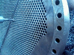
The basic principle of the spiral baffle plate heat exchanger and the form of baffle plate
The idea that the spiral baffle plate heat exchanger is based on the idea that the fluid in the shell side of the shell side is in a continuous spiral flow by changing the layout of the shell side baffle plate. Therefore, the ideal baffle plate should be arranged as a continuous spiral curved surface. However, it is difficult to process the spiral curved surface, and it is difficult to realize the coordination of the heat exchange tube and the baffle plate. Taking into account the convenience of processing, the use of a series of flat plate (called spiral baffle) instead of curved surface connection, the shell side to form an approximate spiral surface, so that the shell side fluid generated approximately continuous spiral flow. Generally speaking, for the processing considerations, a pitch of 2 to 4 pieces of baffle plate, the adjacent baffle plate between the continuous lap and staggered lap two ways, according to the flow channel can be divided into two types of single spiral and double helix.
A heat exchanger baffle directly influences thermal performance, pressure drop, and mechanical integrity of shell-and-tube equipment. Engineers select baffle geometry, spacing, and orientation based on process conditions, fouling tendencies, and allowable pressure losses. Understanding how each parameter interacts helps procurement teams specify the right configuration for long-term reliability and cost-effective operation.
Heat exchanger baffle types and flow characteristics
Different baffle arrangements produce distinct flow patterns on the shell side. The choice between single-spiral, double-helix, and segmental designs affects heat transfer coefficients, vibration risk, and cleaning accessibility. Which type performs best depends on the fluid properties and the duty cycle of the exchanger.
| Baffle Type | Flow Pattern | Heat Transfer Efficiency | Typical Application |
|---|---|---|---|
| Single Spiral | Continuous spiral flow | High (uniform velocity) | High-fouling fluids, viscous media |
| Double Helix | Dual opposing spiral streams | Very high (enhanced mixing) | High-viscosity, polymer processing |
| Segmental (Single-cut) | Cross-flow with reversal | Moderate to high | General chemical, petrochemical |
| Segmental (Double-cut) | Cross-flow with reduced dead zones | High | Large-diameter exchangers |
| Disk-and-Doughnut | Radial flow with high turbulence | Moderate | Gas cooling, condensing duties |
What makes the spiral design particularly attractive is the near-elimination of stagnant zones and the reduction of fouling accumulation. The continuous sweeping action of the fluid along the helical path keeps deposits from settling on tube surfaces. For processes where downtime for cleaning is costly, this characteristic delivers tangible operational savings.
Heat exchanger baffle material selection and durability
Material choice for baffle plates must balance mechanical strength, corrosion resistance, and thermal expansion compatibility with tube materials. Carbon steel offers cost effectiveness for moderate temperatures and non-corrosive services, while stainless steel grades provide superior resistance to oxidation and chemical attack. Which alloy to specify depends on the operating temperature, pH range, and chloride content of the shell-side fluid.
| Material | Max Operating Temperature | Corrosion Resistance | Relative Cost | Common Service |
|---|---|---|---|---|
| Carbon Steel (A516) | 400°C | Moderate (coating required) | Low | Water, steam, light hydrocarbons |
| Stainless 304 | 600°C | High (general purpose) | Medium | Food, pharmaceutical, mild chemicals |
| Stainless 316 | 650°C | Very high (chloride resistant) | Medium-High | Marine, petrochemical, acids |
| Titanium (Grade 2) | 800°C | Excellent (seawater grade) | High | Desalination, offshore, aggressive acids |
| Inconel 625 | 870°C | Excellent (high-temperature) | Very High | High-temp oxidation, sour gas |
How the baffle material interacts with tube materials also affects galvanic corrosion risk. Dissimilar metal combinations should be evaluated carefully, especially in electrolyte-rich environments. Procurement engineers often request detailed material compatibility charts from manufacturers to avoid premature failure.
Heat exchanger baffle design parameters and spacing rules
Baffle spacing, cut size, and orientation are the three primary variables that define shell-side performance. Reducing baffle spacing increases velocity and heat transfer but also raises pressure drop. Conversely, wider spacing lowers pressure drop at the expense of reduced thermal effectiveness. What constitutes an optimal design is a function of the allowable pressure drop and the required duty.
Which spacing rule applies to a specific exchanger depends on the tube bundle natural frequency and the shell-side flow regime. Designers often use the TEMA (Tubular Exchanger Manufacturers Association) guidelines as a starting point, then refine the layout using computational fluid dynamics for critical services. The goal is to achieve uniform flow distribution while avoiding tube vibration that can lead to fretting and tube failure.
What determines heat exchanger baffle efficiency in operation
Operational efficiency of a baffle system is influenced by fouling resistance, flow maldistribution, and bypass streams between the baffle and shell wall. As fouling builds up on the shell side, the effective flow area reduces, causing velocity to increase and pressure drop to rise. How quickly this occurs depends on the fluid cleanliness, operating temperature, and the presence of particulates.
Periodic inspection of baffle condition is essential. Erosion at the tube-baffle intersections, cracking near the support points, and corrosion at the baffle edges are common failure modes. Which inspection method to employ — visual, ultrasonic, or dye-penetrant — depends on the service history and the criticality of the exchanger. Early detection of baffle degradation allows for planned maintenance rather than unplanned shutdowns.
How to choose heat exchanger baffle configuration for your process
Selecting the right baffle configuration starts with defining the process constraints: allowable pressure drop, required heat transfer area, fluid viscosity, and fouling propensity. For clean, low-viscosity fluids, segmental baffles with 25% cut are a reliable choice. For viscous or fouling services, spiral baffles offer better long-term performance because they maintain higher shear stress at the tube surface.
Procurement teams should also consider the manufacturers fabrication capabilities. Complex geometries like double-helix baffles require precision machining and may extend delivery lead times. How these trade-offs align with project schedules and budget constraints often determines the final selection. Consulting with the supplier early in the design phase helps clarify what is feasible without compromising quality.
Which industries rely on heat exchanger baffle technology
Heat exchanger baffles are indispensable across a wide spectrum of industries. In the oil and gas sector, they are used in crude preheat trains, condensers, and reboilers. Chemical plants employ them in reactor effluent coolers and distillation column reboilers. Power generation facilities rely on baffled exchangers for feedwater heating and turbine exhaust condensing. Additionally, the pharmaceutical and food processing industries use sanitary baffle designs that meet strict hygiene standards.
Each industry imposes specific requirements on baffle design. For example, offshore platforms demand compact, corrosion-resistant baffles that withstand wave-induced vibration. Cryogenic applications require materials that maintain toughness at sub-zero temperatures. Understanding these nuances helps buyers communicate their needs clearly to manufacturers and avoid costly overspecification or underperformance.
For detailed technical drawings and custom heat exchanger baffle solutions, consult your equipment supplier with full process data to ensure optimal design and reliable operation over the equipment lifecycle.