

How to enhance the heat transfer performance of HFW finned tubes
Performance Optimization for High Frequency Welded Finned Tubes
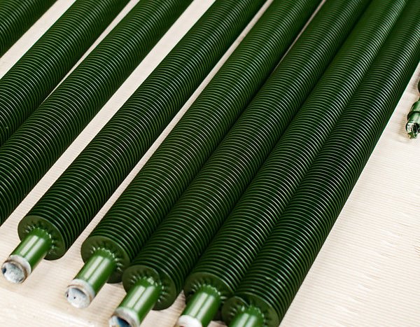
Industrial heat exchange systems depend on component efficiency, and High Frequency Finned Tubes serve as a core element in modern thermal management. Engineers and procurement specialists seek durable, high-performance solutions that deliver consistent heat transfer while minimizing energy consumption and maintenance requirements.
High Frequency Finned Tubes for Thermal Efficiency
The welded bond between fin and base tube, created through high-frequency electrical resistance welding, provides a permanent, low-thermal-resistance interface. This metallurgical bond is stronger than older mechanical methods, allowing for thinner fins, closer spacing, and significant surface area expansion within compact footprints.
Effective enhancement of thermal performance involves a multi-faceted approach, focusing on design, material interaction, and operational parameters. The table below outlines primary factors influencing heat transfer rates in such assemblies.
| Performance Factor | Influence on Heat Transfer | Practical Design Consideration |
|---|---|---|
| Fin Density & Height | Directly increases total surface area exposed to the fluid (air or gas), enhancing convective heat dissipation. | Balance between added surface area and potential airflow resistance. Higher fins require stronger base material. |
| Base Tube Material Conductivity | Determines the rate at which heat travels from the internal fluid (e.g., steam, water) to the fins. | Carbon steel is common for high-pressure steam; copper or aluminum offers superior conductivity for lower-pressure applications. |
| Fin Material & Coating | Affects both conductive heat flow from the tube and corrosion resistance, which maintains efficiency over time. | Aluminum fins provide excellent conductivity and light weight. Galvanized or coated steel fins offer protection in corrosive environments. |
| Fluid Velocity & Turbulence | Higher velocity and induced turbulence on the external (fin side) reduce the boundary layer, increasing convective heat transfer coefficient. | Optimize fan/pump selection and bundle arrangement to achieve desired flow without excessive power consumption. |
| Welded Joint Integrity | A complete, uniform weld ensures minimal thermal contact resistance between fin and tube, a key advantage of the high-frequency process. | Consistent weld quality is critical. Regular inspection verifies there are no gaps acting as insulation barriers. |
Material Selection Insight: For applications where weight and maximum thermal performance are priorities, aluminum high-frequency welded finned tubes are often specified. In high-temperature or high-pressure steam service, carbon or stainless steel tubes with aluminum or steel fins create a robust, reliable assembly.
High Frequency Finned Tubes in System Design
Integrating these components into a larger heat exchanger involves more than just tube selection. The arrangement of the tube bundle, the pitch between tubes, and the clearances for airflow all contribute to the systems overall effectiveness. A staggered tube arrangement often promotes better fluid mixing and turbulence than an in-line arrangement, leading to more efficient heat scavenging.
Surface modification techniques are gaining attention. While keeping fins clean is fundamental, advanced coatings can serve dual purposes: protecting against corrosion and, in some cases, slightly improving emissivity or reducing fouling tendencies, which maintains design performance over longer operational cycles.
| Design Aspect | Standard Configuration | Enhanced Configuration | Impact on Performance |
|---|---|---|---|
| Fin Spacing | 8 - 10 FPI (Fins Per Inch) | 11 - 14 FPI | Increases surface area by 25-40% in same bundle volume, but requires higher fan static pressure. |
| Tube Layout | In-Line Arrangement | Staggered Arrangement | Increases turbulence and heat transfer coefficient by disrupting laminar flow paths. |
| Fin Type | Plain, Smooth Fins | Serrated or Louvered Fins | Breaks up boundary layer more effectively, can improve heat transfer by 15-30% over plain fins. |
| Maintenance Protocol | Reactive Cleaning | Scheduled Air / Water Washing | Prevents efficiency drop-off due to fouling; maintains closer to "as-new" performance. |
For procurement teams, specifying performance requirements clearly is vital. Beyond basic dimensions, providing the desired heat duty, allowable pressure drop on the air/gas side, operating temperatures, and environmental conditions enables manufacturers to recommend the optimal High Frequency Finned Tube configuration.
High Frequency Finned Tubes for Long-Term Operation
Sustaining thermal performance requires attention to the operational environment. In applications with dusty or corrosive atmospheres, fouling can insulate the fin surface. Implementing a regular cleaning schedule using compressed air or controlled water washing is a practical step to preserve efficiency. The robust weld of these tubes withstands such maintenance better than tension-wound fins, which can loosen.
Finally, leveraging modern design tools like Computational Fluid Dynamics (CFD) allows for virtual prototyping of finned tube bundles. This process helps optimize the trade-offs between heat transfer, pressure drop, and material usage before fabrication, reducing development time and ensuring the final installation meets performance targets reliably.
These tubes continue to evolve, offering efficient heat transfer solutions for power generation, HVAC systems, process heating and cooling, and waste heat recovery applications. Their adaptability across materials and designs makes them a versatile choice for engineers aiming to improve system efficiency and reduce lifecycle costs.