


Industrial finned tube|Industrial finned tubes
Industrial finned tube is a widely used heat exchange equipment in the industrial field, and its design and structure allow it to efficiently transfer heat or cooling media. What separates it from a plain pipe is the extra metal surface wrapped around the outside of the pressure tube, and that extra surface is what makes the whole thing work. Below is a closer look at what an Industrial finned tube is built from, how it moves heat, and why so many plants depend on it.
Industrial finned tube structure
The core of the assembly is the internal channel, a metal tube normally made of copper, aluminium, stainless steel or another alloy chosen for high-temperature resistance and corrosion resistance. Everything else is built around that tube, because the tube is the part that holds pressure and carries the working fluid.
Tube
The tube is the pressure boundary. Its wall thickness, outside diameter and material grade decide how much pressure it can hold and which chemicals it can survive. Seamless tube is the usual choice for steam, hot oil and refrigerant duty, while welded tube is common in lower-pressure air heating coils.
Fins
The outer surface of the tube carries a series of small metal fins, usually in the form of elongated strips or flat shapes, arranged parallel to the tube. These fins increase the surface area of the tube, thereby improving heat exchange efficiency. Fin height typically runs from 6 mm to 25 mm, and fin density is described in fins per inch, or FPI.
Fin attachment
How the fin is fixed to the tube decides how much heat can cross the joint. A fin that is only wound on and tensioned relies on mechanical contact, while a fin that is rolled out of the tube wall or welded to it becomes part of the same metal body. This single detail explains most of the price difference between two coils that look identical from the outside.
Industrial finned tube working principle
The working principle of industrial finned tubes is based on the fundamental principles of heat conduction and convective heat transfer. When a hot fluid, usually a liquid or a gas, flows through the interior of the tube, it conducts heat to the fins through the tube wall. The heat on the fins is then transferred to the surrounding medium outside the tube, such as air or another fluid, through convective heat transfer. Because of the fins, the tube has a larger surface area, which allows it to transfer heat more effectively.
Why is the fin always placed on the gas side and not on the liquid side? Because a moving liquid carries heat away far better than air does. Air films are the bottleneck, and adding surface where the bottleneck sits is the cheapest way to raise the overall duty of a coil. Put fins on the water side and the benefit is small; put them on the air side and the same tube length can handle several times the load.
Industrial finned tube materials
Material selection follows the fluid, not the drawing. Which combination fits a given duty depends on the peak metal temperature, the corrosiveness of the gas, and how often the coil can be taken offline for cleaning.
| Tube material | Typical fin material | Practical metal temperature | Where it is used |
|---|---|---|---|
| Carbon steel | Carbon steel, aluminium | Up to about 400 °C | Boiler economisers, flue gas coolers |
| Stainless steel 304 / 316L | Stainless steel, aluminium | Up to about 600 °C | Chemical plants, food drying, waste heat recovery |
| Copper | Copper, aluminium | Up to about 200 °C | Refrigeration, air conditioning coils |
| Copper-nickel 90/10 | Copper-nickel | Up to about 300 °C | Seawater and brackish cooling |
| Titanium | Aluminium, titanium | Up to about 300 °C | Desalination, brine and chloride service |
Industrial finned tube fin types
Two coils can share the same tube diameter and the same footprint and still behave completely differently, simply because the fin was attached in a different way. The table below compares the constructions that appear most often in process and power plants.
| Fin construction | How the fin is attached | Temperature limit | What it suits |
|---|---|---|---|
| Extruded | Fin is rolled out of the tube wall itself | Around 300 °C | No contact resistance, good against fin-side corrosion |
| Embedded, also called G-fin | Fin is wound into a groove and the groove is closed over it | Around 400 °C | Low contact resistance, common in gas-to-liquid duty |
| High frequency welded | Fin is resistance welded to the tube | Above 400 °C | Thermal cycling, soot blowing, dirty flue gas |
| Wrap-on L-foot | Aluminium fin is wrapped and tensioned onto the tube | Around 120 to 150 °C | Air heaters, dryers, low-cost HVAC coils |
| Plate or square fin | Fins are stacked and welded to the tube | Duty dependent | Compact economisers and space-limited retrofits |
Which one is right for a project usually comes down to two questions: how hot does the metal get, and how dirty is the gas? Once those two answers are known, the choice narrows quickly.
Industrial finned tube application areas
Industrial finned tubes are widely used in various industrial sectors, including chemical engineering, power plants, petroleum refining, food processing, cooling systems and air conditioning systems. They are used for heating, cooling, evaporation, condensation and a range of other heat exchange processes.
- Power generation: economisers, air preheaters and condenser coils where flue gas heat has to be recovered before it leaves the stack.
- Chemical processing: process heaters, reboilers and interstage coolers handling corrosive streams.
- Oil and gas: fin fan coolers on refinery overheads and compressor discharge lines.
- Food and beverage: drying tunnels, baking ovens and refrigeration evaporators where hygiene and cleanability matter.
- HVAC and cooling: chilled water coils, condensers and evaporative cooling towers.
Industrial finned tube advantages
The reason a finned tube replaces several bare tubes in the same duty is straightforward. A larger surface area means more heat moves for the same amount of metal, and the fan or pump that pushes the gas across the coil does not have to work as hard.
- High heat transfer efficiency: the finned surface can be ten to twenty times the bare tube area, so a shorter coil does the same job.
- Corrosion resistance: tube and fin grades can be matched to the environment, and dissimilar metals can be separated where a galvanic couple would be a problem.
- Customisability: finned tubes can be customised in size, materials and fin shapes to meet the specific requirements of different applications.
- Smaller footprint: a compact coil means a smaller duct, a lighter support structure and less structural steel in the plant.
- Lower operating cost: less fan power and lower pressure drop across the coil translate directly into electricity savings over the life of the unit.
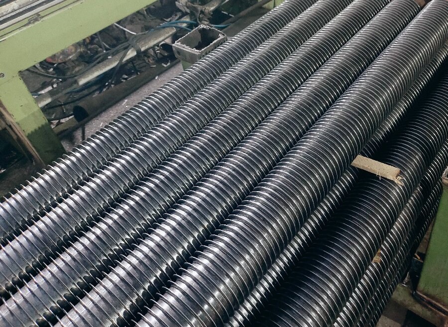
Industrial finned tube
Industrial finned tube maintenance
Finned tubes require regular maintenance and cleaning to prevent dirt and corrosion from affecting their performance. Cleaning can be done through flushing, scraping or chemical cleaning, and the method chosen has to match the fin density, because a tightly finned coil cannot be reached with a scraper.
- Steam or compressed air blowing suits loose dust and works well on wide fin spacing.
- High-pressure water washing removes sticky deposits but must be followed by drying to stop corrosion at the fin root.
- Chemical cleaning is reserved for scale and hard deposits, and the solution has to be compatible with both the tube and the fin alloy.
- Soot blowers are used on-line in boilers, and their placement is decided at the design stage rather than after commissioning.
What shortens the life of a coil most often is not the gas itself, but a cleaning schedule that was written for a clean fuel and never updated when the fuel changed.
Industrial finned tube questions
What is an industrial finned tube made of?
The pressure tube is usually carbon steel, stainless steel 304 or 316L, copper, copper-nickel or titanium. The fins are most often aluminium, copper, carbon steel or stainless steel, picked to match the flue gas or air that will pass over them.
How do you choose the fin pitch on an industrial finned tube?
A tighter fin pitch packs more surface into the same tube length, but it also traps ash and dust faster. Clean air or refrigerant coils can run at 8 to 12 fins per inch, while dirty flue gas streams are usually built at 4 to 6 fins per inch so that soot blowers and wash water can reach the gap between fins.
Why does an industrial finned tube foul more quickly than a bare tube?
The fins create narrow channels where particles settle and where the gas velocity drops close to the metal surface. Once a layer of ash or scale forms at the fin root, it acts as an insulating blanket and the heat transfer coefficient falls sharply, so cleaning intervals matter as much as the original design.
Can an industrial finned tube be repaired on site?
Small sections of damaged finning can be cut out and replaced by welding a new finned length into the header circuit, but a tube that has lost its bond between fin and wall cannot be restored by surface treatment. In most plants the practical answer is to replace the whole coil or the affected tube row.
What is the difference between an extruded fin and a welded fin on an industrial finned tube?
An extruded fin is lifted out of the tube wall itself, so there is no contact resistance and no bimetallic gap, but it is limited to softer metals and moderate temperatures. A welded fin is attached by resistance welding, which survives higher metal temperatures and thermal cycling, which is why boiler economisers and superheaters use welded construction.
Whether a plant is heating a building, drying a product or pulling waste heat out of a flue, the fin type, the alloy and the fin spacing decide whether the coil still performs in year fifteen the way it did in year one. Those three decisions, made together rather than one at a time, are what separate a coil that lasts from one that is replaced twice a decade.