


How inner finned tube improves heat exchanger performance
Heat exchangers represent a major capital expense across chemical, refinery, power and refrigeration facilities. In refineries alone, they can account for up to 35 % of total project investment. Even modest thermal improvements can yield meaningful long‑term savings. Inner‑finned tubes have become a proven option to address two real‑world engineering challenges: higher heat flux requirements and limited available equipment space.
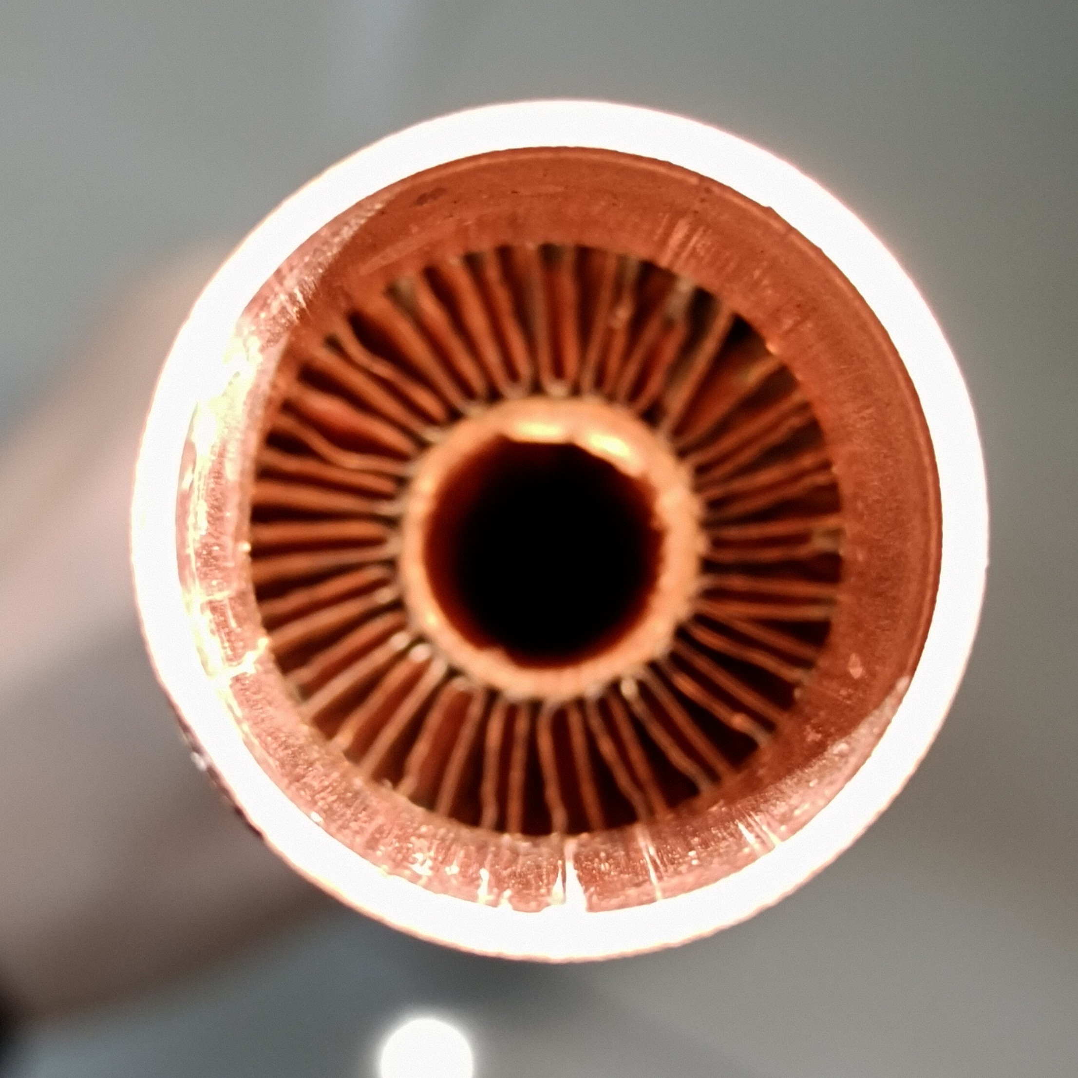
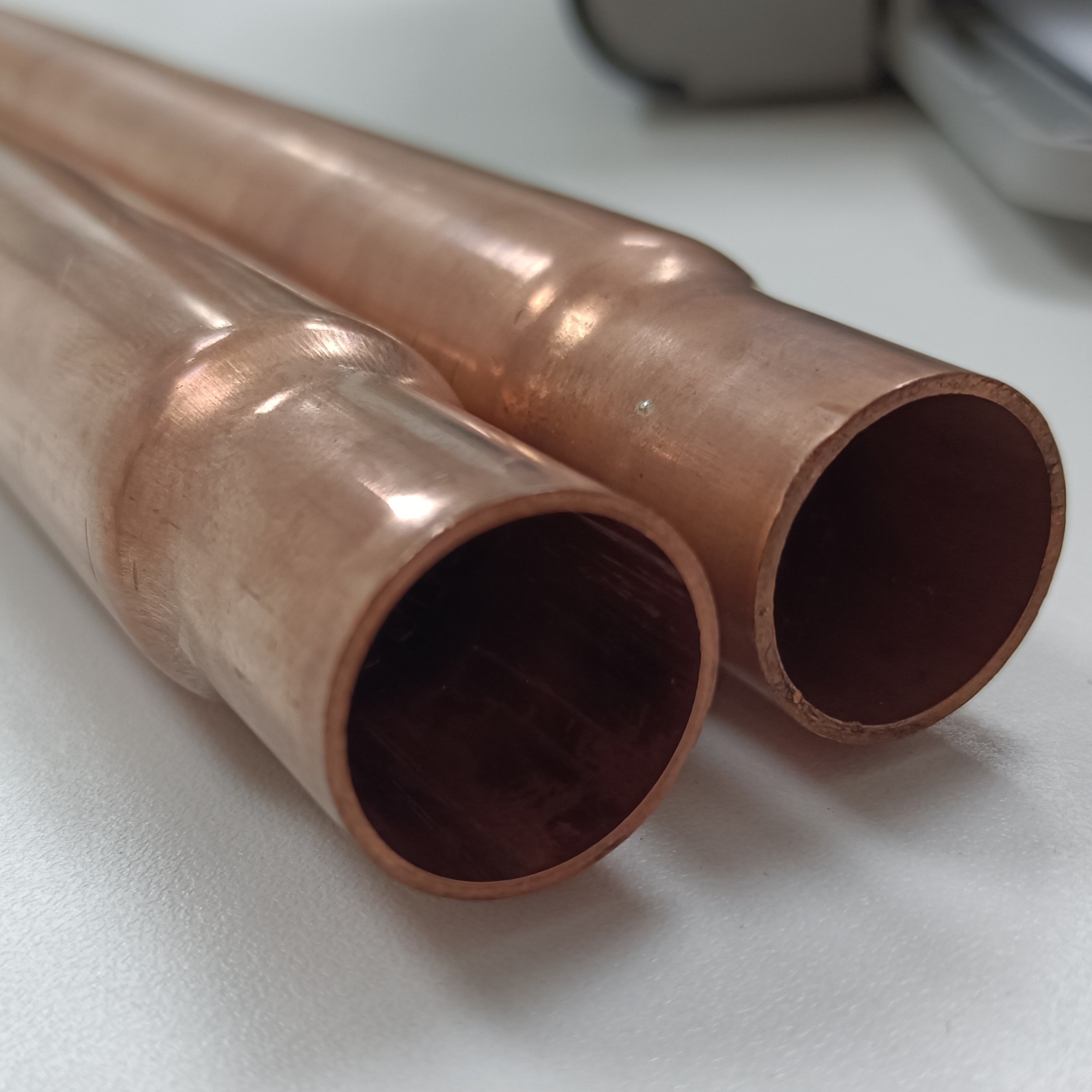
What inner finned tube does to heat transfer area
A plain tube relies on its smooth inner wall – the area is simply π×D×L. Inner fins fold that wall into multiple extended surfaces. Depending on fin density and geometry, the internal surface area can expand by 40 % to over 300 %. For many commercially available inner finned tubes, the internal finning ratio (fin area / bare tube area) ranges from 4 to 6, which directly translates into a 3‑ to 4‑fold increase in the inside heat transfer coefficient compared to a smooth tube of the same diameter.
Increased surface area is only one benefit. Equally important is flow disturbance created by inner fins. Fluid passing over fins experiences repeated flow separation and reattachment, generating secondary flows and transverse mixing. This thins the thermal boundary layer, reducing thermal resistance. Tests comparing corrugated inner finned tubes with plain tubes show that the enhancement is particularly pronounced at low flow velocities – exactly where conventional tubes struggle.
Typical performance gains (laboratory and pilot‑scale tests):
- Refrigerant (R134a) evaporation with spiral inner fins – heat‑transfer coefficient +60 % to +100 %, pressure drop nearly same as plain tube.
- Single‑phase water‑water with longitudinal fins – overall U‑value +30 %, pressure drop +20 % (moderate).
- High‑pressure feedwater heaters using integral fins – tested overall U +43 %, pressure drop +18 %.
- Air‑to‑air at 600 °C with nickel‑brazed fins – overall heat transfer +50 %, pressure drop +25 % (manageable with proper fan selection).
These values come from lab testing; real‑world performance will shift with fouling, flow regime and fin geometry. Always verify with site‑specific data.
Which equipment size reduction can inner finned tube deliver
Improved tube‑level thermal performance yields fewer tubes in the bundle, smaller shell diameters and reduced overall weight. For a given duty, an inner finned tube heat exchanger typically occupies only 45–75 % of the volume of an equivalent outer‑finned tube unit, and about 20–30 % of a plain‑tube bundle. One test rig showed that the compactness factor (m² of heat transfer area per m³ of exchanger volume) of an internally finned insert-type exchanger reaches 12 times that of a conventional shell‑and‑tube with plain tubes.
Thanks to this compact design, projects can cut steel usage, shrink foundation requirements, and simplify equipment layout in congested process areas. A plant engineer can often replace a 10‑meter long bare‑tube bundle with a 6‑meter inner finned bundle, freeing up space for maintenance access or additional equipment.
How inner finned tube manages pressure drop trade‑offs
Designers frequently raise pressure‑drop concerns: added fin structures introduce flow friction. How much penalty occurs heavily depends on fin geometry. Multi‑directional corrugated inner fins, for instance, enhance heat transfer while keeping longitudinal flow resistance within a predictable range – in some designs, the pressure drop increase is less than 15 % for a 40 % gain in heat transfer. Spiral inner finned tubes used with refrigerants show a pressure drop nearly identical to plain tubes, because the spiral path promotes swirl without creating abrupt obstructions.
For applications where pressure drop is critical, designers can select low‑fin density tubes or saw‑tooth fin profiles with open ends. Newer variants like dimple‑protruded inner fins are being evaluated for their ability to maintain high heat transfer with even lower flow resistance than traditional finned surfaces.
Pressure drop ratios (finned vs. plain) at Re ≈ 10k – typical ranges:
- Helical (spiral, low angle, 16 fins/in): ΔP ratio 1.05–1.10 – used in refrigerant condensers and chillers.
- Longitudinal straight fins (20 fins/in): ΔP ratio 1.20–1.30 – common for single‑phase liquids and viscous fluids.
- Corrugated/wavy (12 fins/in): ΔP ratio 1.25–1.40 – preferred for gas‑to‑gas high‑temperature duties.
- Saw‑tooth interrupted (18 fins/in): ΔP ratio 1.12–1.18 – often used in air‑cooled heat exchangers.
These are laboratory benchmarks. Actual ΔP depends on operating Reynolds number, fouling and fin manufacturing tolerances.
What inner finned tube offers for high‑temperature and corrosive streams
Not all enhancement techniques survive harsh conditions. Inner finned tubes built with nickel‑base brazing or diffusion bonding can achieve very high fin‑to‑tube wall contact, minimising interfacial thermal resistance. These tubes operate reliably at up to 600 °C (1112 °F) under high‑velocity gas flow and in the presence of corrosive flue gases. The integral construction (fins machined from the tube wall) further avoids the risk of fin loosening due to differential thermal expansion – a common failure mode in mechanical finned tubes.
For processes exposed to sulfuric‑acid dew‑point corrosion, inner‑finned tubes made from materials such as 316L or duplex stainless steel deliver substantially longer service life compared to plain carbon‑steel tubes, while retaining improved heat transfer performance.
How inner finned tube performs in field installations – typical observations
Typical field observations for spiral inner‑finned DX evaporators show overall heat‑transfer coefficient improvements around 50–60 %. In such retrofits, tube count may be reduced by roughly one‑third while keeping cooling capacity unchanged, with pressure drop staying within existing compressor limits.
Some continuous‑process installations with petal‑style inner‑fin geometries report annual electricity savings near 270 000 kWh per unit, alongside corresponding cuts in coal consumption and CO₂ output. These figures are application‑specific and cannot be guaranteed for every project.
In power plant auxiliary coolers, longitudinal inner finned bundles have achieved a 30 % higher overall U‑value compared to plain bundles of the same shell size, enabling higher cooling water outlet temperature and reduced cooling tower load. Boiler economisers with inner fins have lowered exhaust gas temperature by 10–12 °C, improving overall efficiency by about 1 percentage point in some installations. All these results are drawn from published industry data and should be validated with your own process conditions.
Which inner finned tube geometry fits your process
Spiral / helical fins work well for two‑phase boiling or condensation duties, as well as single‑phase flows benefiting from swirl effects, with relatively low pressure‑drop penalty.
Longitudinal straight fins lend themselves to mechanical cleaning. They are a solid pick for viscous or fouling‑prone fluids, though thermal enhancement remains moderate.
Corrugated / wavy fins generate high turbulence and are well suited for gas‑side duties; expect higher ΔP, which may be acceptable if pumping capacity is available.
Interrupted (saw‑tooth) fins periodically restart the boundary layer, delivering very high heat transfer per unit pressure drop. They are often chosen for air‑side or low‑density gas applications.
How inner finned tube is manufactured and what materials are available
Two primary routes: (1) integral – fins are formed by cold drawing or extrusion from the tube wall, producing a seamless fin‑tube monolith; (2) brazed or welded – fins are attached to the inner wall using high‑temperature brazing. Integral tubes offer maximum reliability and zero contact resistance, but they are limited to ductile metals (copper, aluminium, low‑carbon steel). Brazed construction allows combinations like copper fins inside steel tubes, or stainless steel fins for corrosion resistance.
Common materials: copper (excellent thermal conductivity, used in HVAC), aluminium (lightweight), carbon steel (cost‑effective for water/steam), stainless steel 304/316 (for corrosive or sanitary services), and nickel alloys (for high‑temperature or aggressive chemical streams). The choice affects not only heat transfer but also fouling behaviour – smooth fin surfaces with electropolishing can reduce particulate adhesion.
What about cleaning and fouling in inner finned tubes
Fouling is a legitimate concern – narrow channels between fins can trap debris or scale. However, proper design mitigates this: for fluids prone to fouling, choose low‑fin density (8‑12 fins per inch) and straight longitudinal fins rather than tight spirals. Some installations use online brushing systems (with specially designed brushes that traverse the finned bore) or chemical cleaning‑in‑place. In practice, many operators report that the higher shear stress caused by increased turbulence actually reduces fouling rates compared to plain tubes, because the boundary layer is thinner and less deposition occurs. A chemical plant that switched to inner finned tubes in a fouling service saw the cleaning interval extend from 6 months to 18 months. Results will vary with fluid quality and fouling chemistry.
Inner‑finned tubes are not a universal fix for every heat‑transfer challenge. Good outcomes come from careful selection of fin geometry, material and fin density aligned with your process fluid, operating temperature and allowable pressure‑drop budget. When specified properly, they can deliver measurable benefits: smaller equipment footprint, lower energy use and extended maintenance cycles.